
Cassette Ductless Data Sheet

16
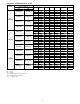
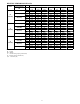
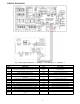
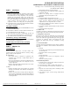
WIRING DIAGRAMS
Fig. 6 – Wiring Diagram 38MAQB09- - - 3 / 40MBQ09C- - 3 AND 38MAQB12- - - 3 / 40MBQ12C - - 3
Indoor unit Outdoor unit
CODE PART NAME CODE PART NAME
CN1 Input: 230VAC High voltage Connection of the terminal CN31
Output:Pin5&6(12V) Pin1-Pin4:Pulse
waveform,(0-12V)
CN3 Output: 0-5VDC Connection of the CCM CN21 Input:Pin3-4 (3.3V) Pin2(0V),Pin1,Pin5(0-3.3V)
P1 Output: 0V Connection of the earth CN22 Input:Pin1 (3.3V) Pin2(0-3.3V)
CN5 Output: 1-5VDC Connection of the Water level switch CN37 Output: 230VAC High voltage
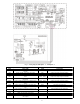
CN6
Output: 5VDC Connection of the Room and Pipe
temperature
CN9-1,CN32-1 Output: Connection of the high voltage
CN10A Output: 12VDC Connection of the Display board CN1 Input:230VAC High voltage
CN13 Output: 220VAC High voltage Connection of the Pump CN2 Input:230 VAC High voltage
CN14 Output: 12VDC Connection of the Swing motor CN3 Connection to the earth
CN15 Output: 320VDC High voltage Connection of the DC Fan CN16 Output: Connection of the high voltage
CN16 Output: 320VDC High voltage Connection of the Reactor CN26,CN27 Output: High voltage for 4-way control
CN23 Output: 1-12VDC Connection of the Remote switch CN7 Output: Pulse(0-320VDC) for DC FAN
CN33 Output: 0V Connection of the Alarm UVW Output: Pulse(0-320VDC) for COMPRESSOR
CN40 Output: 12VDC Connection of the Wire controller
CN110
Output: 24VDC between Pin2 of CN1 connection of the S
signal