
Cassette Ductless Data Sheet

12
APPLICATION DATA
UNIT SELECTION
Select equipment to either match or be slightly less than anticipated
peak load. This provides better humidity control, fewer unit cycles,
and less part- load operation.
For units used in spaces with high sensible loads, base equipment
selection on unit sensible load, not on total anticipated load. Adjust
for anticipated room wet bulb temperature to avoid undersizing
equipment.
UNIT MOUNTING (INDOOR)
Refer to unit Installation Instructions for further details.
Unit leveling - For reliable operation, units should be level in all
planes. Align and level the unit by adjusting the nuts and
lock - - nuts on the threaded hangers.
Clearance - A minimum of 12 inches (304.8 mm) of clearance is
required in the false ceiling.
Unit location - Placing the unit in the center of the room will
provide the best air circulation and comfort.
The unit return and discharge should not be obstructed by anything
which may cause unit short cycling or air recirculation.
Installation Template - Fan coil units are supplied with a
cardboard template to help match the position of the hangers,
refrigerant lines, condensate drain pipe and power supply cable.
UNIT MOUNTING (OUTDOOR)
Refer to unit Installation Instructions for further details.
Unit leveling - For reliable operation, units should be level in all
planes.
Clearance - Minimum clearance, as shown in Fig. 4, must be
provided for airflow. The condensing units are designed for
free- blow application. Air inlets and outlets should not be
restricted.
Unit location - A location which is convenient to installation and
not exposed to strong wind.
A location which can bear the weight of outdoor unit and where
the outdoor unit can be mounted in a level position.
Do not install the indoor or outdoor units in a location with special
environmental conditions. For those applications, contact your
Carrier representative.
SUPPORT
Adequate support must be provided to support the weight of all fan
coils. Refer to the Physical Data section for fan coil weights, and
the base unit dimensional drawings for the location of mounting
brackets.
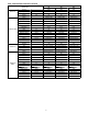
SYSTEM OPERATING CONDITIONS
Operating Range
Min / Max °F (°C)
Cooling Heating
Outdoor DB 4 / 122 (-20 / 50) 4 / 86 (-20 / 30)
Indoor DB 63 / 90 (17 / 32) 32 / 86 (0 / 30)
Indoor WB 59 / 84 (15 / 29) 4.1 / 70.7 (-15.5 / 21.5)
Non-Operating Temperature Range
Min / Max °F (°C)
Indoor/O utdoor DB 32 / 86 (0 / 30)
NOTE: Reference the Product Installation Instructions for mor e information.
METERING DEVICES
These units have capillary tube metering devices in the outdoor
unit.
DRAIN CONNECTIONS
Install drains to meet local sanitation codes. The in- ceiling cassette
is supplied with a pump that is capable of lifting the water 29.5in
(750mm) above the top of the unit. A downward sloped
condensate drain pipe can be used to dispose of water.
See physical dimension tables for drain sizes.
REFRIGERANT LINES
General refrigerant line sizing:
1. The 38MAQ units are shipped with a full charge of R410A
refrigerant. All charges, line sizing, and capacities are based
on runs of 25 ft (7.6 m). For runs over 25 ft (7.6 m),
consult long- line section on this page for proper charge
adjustments.
2. Refrigerant lines should not be buried in the ground. If it is
necessary to bury the lines, not more than 36 - in (914 mm)
should be buried. Provide a minimum 6 - in (152 mm)
vertical rise to the service valves to prevent refrigerant
migration.
3. Both lines must be insulated. Use a minimum of 1/2- in.
(12.7 mm) thick insulation. Closed - cell insulation is
recommended in all long- line applications.
4. Special consideration should be given to isolating
interconnecting tubing from the building structure. Isolate
the tubing so that vibration or noise is not transmitted into
the structure.
Long Line Applications, 38MAQ Units:
1. No change in line sizing is required.
2. Add refrigerant per table below.
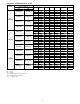
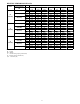
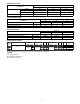
ADDITIONAL CHARGE TABLE
Unit
Size
Total Line
Length ft
Additional Charge, oz/ft.
ft (m)
Min Max
10 - 25
(3 - 8)
>25 - 82
(8 - 25)
>82 - 98
(25 - 30)
9
10
82
None
0.27
12
18 82
0.43 0.43