
Operating instructions


b. InstallremovedclampandplugintoUPPERcollectorbox
&ainrobe(bluelabel)whichwasconnectedtocondensate
trap.
c.ConnectLOWERcollectorboxdrainconnectiontocon-
densatetrap.
(1.)CondensateTrapLocatedonLeftSideofCasing
(a.)ConnectLOWERcollectorbox&aintube(blue
andwhitestripedlabel)tocondensatetrap.Tube
doesnotneedtobecut.
(b.)Clamptubetopreventanycondensateleakage.
(2.)CondensateTrapLocatedonRightSideofCasing
(a.)Installdraintubecoupling(factory-suppliedin
loosepartsbag)intocollectorboxdraintube
(blueandwhitestripedlabel)whichwasprevi-
ouslyplugged.
(b.)Connectlargerdiameter&aintube(factoW-
suppliedinloosepartsbag)to&ainrobecou-
pling,extendingcollectorboxdraintubefor
connectiontocondensatetrap.
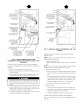
(c.)Routeextendedcollectorbox&ainrobedirectly
fromcollectorbox&aintocondensatetrapas
showninFig.9.
(d.)Determineappropriatelengthandcut.
(e.)Connecttocondensatetrap.
(f.)Clamprobetopreventanycondensateleakage.
2. Inducer Housing Drain Tube
a. Remove factory-installed cap and clamp from LOWER
inducer housing drain connection.
b. Remove and discard UPPER (molded) inducer housing
&ain tube which was previously connected to condensate
trap.
c. Install cap and clamp on UPPER inducer housing &ain
connection where molded &ain tube was removed.
d. Use inducer housing &ain tube (violet label and factory-
supplied in loose parts bag) to connect LOWER inducer
housing &ain connection to the condensate trap.
e. Connect inducer housing drain connection to condensate
trap.
(1.) Condensate Trap Located on Left Side of Casing
(a.) Detemfine appropriate length and cut.
(b.) Connect robe to condensate trap.
(c.) Clamp tube to prevent any condensate leakage.
(2.) Condensate Trap Located on Right Side of Casing
(a.) Route inducer housing drain tube (violet label)
directly from inducer housing to condensate trap
as shown in Fig. 9.
(b.) Determine appropriate length and cut.
(c.) Connect robe to condensate trap.
(d.) Clamp tube to prevent any condensate leakage.
3. Relief Port Tube
Refer to Pressure Switch Tubing section for connection procedure.
CONDENSATE TRAP FIELD DRAIN ATTACHMENT
Refer to Condensate Drain section for recommendations and
procedures.
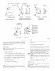
PRESSURE SWITCH TUBING
One collector box pressure robe (pink label) is t_actory connected to
the pressure switch for use when fi_rnace is installed in UPFLOW
applications This tube MUST be disconnected and used for the
condensate trap relief port robe. The other collector box pressure
tube (green label) which was factory connected to the condensate
trap relief port connection MUST be connected to the pressure
switch in DOWNFLOW or HORIZONTAL RIGHT applications.
NOTI=: See Fig. 8 or 9 or robe routing label on main fumace door
to check for proper connections.
i. Disconnect collector box pressure tube (pink label) attached to
pressure switch.
2. Extend collector box pressure tube (green label) which was
previously connected to condensate trap relief port connection
by splicing to small diameter robe @actory-supplied in loose
parts bag).
3. Connect collector box pressure tube (green label) to pressure
switch connection labeled COLLECTOR BOX.
4. Extend collector box pressure tube (pink label) which was
previously connected to pressure switch by splicing to remain-
ing small diameter robe @actory-supplied in loose parts bag).
5. Route this extended tube (pink label) to condensate trap relief
port connection.
6. Determine appropriate length, cut, and connect tube.
7. Clamp tube to relief port connection.
CONDENSATE TRAP FREEZE PROTECTION
Refer to Condensate Drain Protection section for recommenda-
tions and procedures.
Step 4---Horizontal Left (Supply-Air Discharge)
Applications
A horizontal left furnace application is where fln'nace blower is
located to the right of combustion and controls section of furnace,
and conditioned air is discharged to the left.
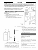
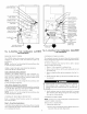
CONDENSATE TRAP LOCATION
The condensate trap must be removed from the fi_ctory-installed
blower shelf location and relocated in selected application location
as shown in Fig. 2 or 10.
To relocate condensate trap from the blower shelf to desired
location, perform the following:
i. Remove 3 tubes connected to condensate trap.
2. Remove trap l}om blower shelf by gently pushing tabs inward
and rotating trap.
3. Install casing hole filler cap (factory-supplied in loose parts
bag) into blower shelf hole where trap was removed.
4. Install condensate trap into left-hand side casing hole by
inserting robe connection stubs through casing hole and
rotating until tabs snap into locking position.
5. Fill unused condensate trap casing holes with plastic filler
caps (factory-supplied in loose parts bag).
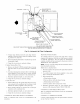
CONDENSATE TRAP TUBING
NOTI=: See Fig. 10 or tube routing label on main fl_rnace door to
check for proper connections.
i. Collector Box Drain Tube
a. Install drain tube coupling (factory-supplied in loose parts
bag) into collector box drain tube (blue label) which was
previously connected to condensate trap.