
Operating instructions


BLOWERSHELFT- FURNACE
_DOOR
CONDENSATE \
TRAP (tNSlDE) L I
FIELD ii_
DRAIN
CONN
TUBE LOCATION
CONDENSATE TRAP --
DRAIN TUBE LOCATION
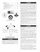
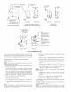
UPFLOW APPLICATIONS
i; CONDENSATE
TRA;uRNAC E i Z
SIDE, i"
261/4 1 /2
SIDE VIEW FRONT VIEW
DOWNFLOW AND ALTERNATE
EXTERNAL UPFLOW APPLICATIONS
_ FURNACE
OOR
FIELD[--/ 4
DRAIN
CONN
-- FURNACE
SIDE
¾
END VIEW FRONT VIEW
HORIZONTAL
APPLICATIONS
7
(OPTIONAL) /
.,.i 11/2 !
GUIDES
(WHEN USED)
FRONT VIEW SIDE VIEW
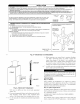
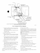
¼0D
COLLECTOR BOX TO
TRAP RELIEF PORT
½0D
INDUCER HOUSING
DRAIN CONNECTION
OD
COLLECTORBOX
DRAIN CONNECTION
SCREW HOLE FOR
UPFLOW OR DOWN-
FLOW APPLICATIONS
(OPTIONAL)
V_-IN PVC OR CPVC
Fig. 5--Condensate Trap
A93026
tube is used to extend the condensate trap drain connection to the
desired furnace side for field drain attachment. See Condensate
Trap Tubing (Factory-Shipped Orientation) section for drain robe
extension details. (See Fig. 5.)
CONDENSATE TRAP TUBING (FACTORY-SHIPPED
ORIENTATION)
NOTE: See Fig. 6 or robe routing label on main furnace door to
confirm location of these robes.
i. Collector Box Drain, Inducer Housing Drain, Relief Port, and
Pressure Switch Tubes.
These tubes should be _actory attached to condensate trap and
pressure switch ready for use in UPFLOW applications. These
robes can be identified by their connection location and also
by a color label on each tube. These robes are identified as
follows: collector box &ain robe (blue label), inducer housing
drain tube (violet label or molded), relief port tube (green
label), and pressure switch tube (pink label).
2. Condensate Trap Drain Tube
The condensate trap drain connection must be extended for
field attachment by doing the following:
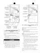
a. Determine location of field drain connection. (See Fig. 2 or
6.)
NOTE: Ifintemal filter or side Filter.Media Cabinetis used, &ain
tube should be located to opposite side of casing from remm duct
attachment to assist in filter removal.
b. Remove and discard casing drain hole plug button from
desired side.
c. Install &ain tube coupling grommet (factory-supplied in
loose parts bag) in selected casing hole.
d. Slide &ain tube coupling (_actory-supplied in loose parts
bag) through grommet ensuring long end of coupling faces
blower.
e. Cement 2 factory-supplied 1/2-in. street CPVC elbows to
the rigid drain tube connection on the condensate trap. (See
Fig. 6.) These elbows must be cemented together and
cemented to condensate trap drain connection.
NOTE: Failure to use CPVC elbows may allow &ain to kink and
prevent draining.
f. Connect larger diameter drain robe and clamp (factory-
supplied in loose parts bag) to condensate trap and clamp
securely.
g. Route robe to coupling and cut to appropriate length.
h. Attach tube to coupling and clamp securely.
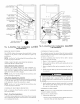
CONDENSATE TRAP LOCATION (ALTERNATE UPFLOW
ORIENTATION)
An alternate location for the condensate trap is the left-hand side
of casing. (See Fig. 2 and 7.)
NOTE: If the alternate left-hand side of casing location is used,
the fi_ctory-connected &ain and relief port tubes nmst be discon-
nected and modified for attachment. See Condensate Trap Tubing