
Operating instructions
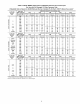
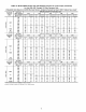
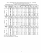
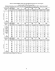
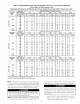
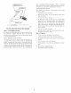
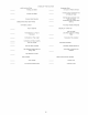

Table 10--Model 58MXA Orifice Size and Manifold Pressure for Correct Input (Continued)
for Use With 140 Size Furnaces Only
(Tabulated Data Based on 23,000 Btuh per Burner, Derated 2% for Each 1000 Ft Above Sea Level) *
ALTITUDE
RANGE
(FT)
4001
O to
(,3
:5 5000
9%
derate
ALTITUDE
RANGE
(ft)
>, 5001
O
to
6000
11%
derate
ALTITUDE
RANGE
(ft)
6001
O to
u_
:5 7000
13%
derate
AVG GAS
HEAT VALUE
AT ALTITUDE
(BTU/CU FT)
725
750
775
800
825
850
875
900
925
950
AVG GAS
HEAT VALUE
AT ALTITUDE
(Btu/cu ft)
700
725
750
775
800
825
850
875
900
925
950
975
1000
AVG GAS
HEAT VALUE
AT ALTITUDE
(Btu/cu ft)
650
675
700
725
750
775
800
825
850
875
SPECIFIC GRAVITY OF NATURAL GAS
0.68 0.60 0.62 0.64 0,66
Orifice Manifold Orifice Manifold Orifice Manifold Orifice Manifold Orifice Manifold
No. Pressure No. Pressure No. Pressure No. Pressure No. Pressure
41 3.6 4! 3.7 41 3.8 40 3.6 40 3.8
42 3.7 42 3.8 41 3.6 41 3.7 41 3.8
42 3.5 42 3.6 42 3.7 42 3.8 41 3.6
42 3.3 42 3.4 42 3.5 42 3.6 42 3.7
43 3.7 42 3.2 42 3.3 42 3.4 42 3.5
43 3.5 43 3.6 43 3.8 42 3.2 42 3.3
43 3.3 43 3.4 43 3.6 43 3.7 43 3.8
43 3.1 43 3.3 43 3.4 43 3.5 43 3.6
43 3.0 43 3.1 43 3.2 43 3.3 43 3.4
43 2.8 43 2.9 43 3.0 43 3.1 43 3.2
SPECIFIC GRAVITY OF NATURAL GAS
0.68 0.60 0,62 0.64 0.66
Orifice Manifold Orifice Manifold Orifice Manifold Orifice Manifold Orifice Manifold
No. Pressure No. Pressure No. Pressure No. Pressure No. Pressure
41 3.5 41 3.7 41 3.8 40 3.6 40 3.7
42 3.7 42 3.8 41 3.5 4! 3.6 41 3.8
42 3.4 42 3.5 42 3.7 42 3.8 41 3.5
42 3.2 42 3.3 42 3.4 42 3.5 42 3.7
43 3.7 43 3.8 42 3.2 42 3.3 42 3.4
43 3.6 43 3.6 43 3.7 43 3.8 42 3.2
43 3.3 43 3.4 43 3.5 43 3.6 43 3.7
43 3.1 43 3.2 43 3.3 43 3.4 43 3.5
43 2.9 43 3.0 43 3.1 43 3.2 43 3.3
43 2.7 43 2.8 43 2.9 43 3.0 43 3.1
43 2.6 43 2.7 43 2.8 43 2.9 43 3.0
43 2.5 43 2.6 43 2.6 43 2.7 43 2.8
43 2.3 43 2.4 43 2.5 43 2.6 43 2.7
SPECIFIC GRAVITY OF NATURAL GAS
0.68 0.60 0,62 0.64 0.66
Orifice Manifold Orifice Manifold Orifice Manifold Orifice Manifold Orifice Manifold
No. Pressure No. Pressure No. Pressure No. Pressure No. Pressure
41 3.8 40 3.6 40 3.7 40 3.8 39 3.7
41 3.5 41 3.6 41 3.7 40 3.6 40 3.7
42 3.6 42 3.7 41 3.5 41 3.6 41 3.7
42 3.4 42 3.5 42 3.6 42 3.7 42 3.8
43 3.8 42 3.3 42 3.4 42 3.5 42 3.6
43 3.6 43 3.7 43 3.8 42 3.3 42 3.4
43 3.4 43 3.5 43 3.6 43 3.7 43 3.8
43 3.2 43 3.3 43 3.4 43 3.5 43 3.6
43 3.0 43 3.1 43 3.2 43 3.3 43 3.4
43 2.8 43 2.9 43 3.0 43 3.1 43 3.2
* Orifice numbers 43 shown in BOLD are factory installed
Percents of derate are based on midpoints of U.S. altitude ranges
NOTE: This furnace has been approved for a manilbld pressure
of 3.2 in. wc to 3.8 in. wc when installed at altitudes up to 2000 ft.
For altitudes above 2000 ft, the manifold pressure can be adjusted
from 2.0 in. wc to 3.8 in. wc. If manifold pressure is outside this
range, change burner orifices to obtain pressure in this range.
r:l ['_=ii[']'_
DO NOT bottom-out gas valve regulator adjusting screw.
This can result in unregulated manifold pressure and result in
excess overfire and heat exchanger fuilures.
NOTE: If orifice hole appears damaged or it is suspected to have
been re&illed, check orifice hole with a numbered &ill bit of
45
con'ect size. Never re&ill an orifice. A burr-free and squarely
aligned orifice hole is essential for proper flame characteristics.
DO NOT re&ill orifices. Improper &illing (burrs, out-of-
round holes, etc.) can cause excessive burner noise and
misdirection of bumer flames. This can result in flame
impingement of burners and heat exchangers causing failures.
(See Fig. 58.)
e. Replace gas valve regulator adjustment screw seal cap.
f. Replace burner enclosure front and verify adjusted gas
input rate using method outlined in item 3.