
Operating instructions
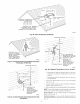
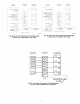
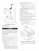

Notes For Figure 48-54
i. Heat pump MIST have a high pressure switch for dual fuel applications.
2. Refer to outdoor equipment Installation Instructions for additional infomlation and setup procedure.
3. Select the "ZONE" position on the two-speed heat pump control.
4. Outdoor Air Temperature Sensor nmst be attached in all dual fuel applications.
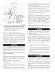
5. Dip switch No. 1 on Thennidistat should be set in OFF position for air conditioner installations. This is factory default.
6. Dip switch No. 1 on Thennidistat should be set inON position for heat pump installations.
7. Dip switch No. 2 on Thennidistat should be set in OFF position for single-speed compressor operation. This is fi_ctory defimlt.
8. Dip switch No. 2 on Thennidistat should be set in ON position for two-speed compressor operation.
9. Configuration Option No. 10 "Dual Fuel Selection" nmst be tumedON in all dual fuel applications.
i0. NO connection should be made to the furnace HUM terminal when using a Thermidistat.
11. The RVS Sensing terminal "L" should not be connected. This is internally used to sense defrost operation.
12. DO NOT SELECT the "FURNACE INTERFACE" or "BALANCE POINT" option on the two-speed heat pump control board. This is
controlled internally by the Thennidistat_ual Fuel Themlostat.
13. Dip switch D on Dual Fuel Thermostat should be set in OFF position for single-speed compressor operation. This is factory default.
14. Dip switch D on Dual Fuel Thermostat should be set in ON position fbr two-speed compressor operation.
be adjusted to FAN, HEAT, or COOL speed) at the thermo-
stat. Factory default is FAN" speed. Terminal EAC-1 is
energized as long as the blower motor BLWM is energized.
During a call for heat, the blower BLWM will stop during
igniter warm-up (17 seconds), ignition (7 seconds), and
blower-ON delay (66 or 45 seconds for 040 through 120 sizes
or for 140 size), allowing the furnace heat exchangers to heat
up more quickly, then restarts at the end of the blower-ON
delay period at HEAT speed.
In heating, the furnace control CPU will hold the blower
motor BLWM at HEAT speed during the selected blower-OFF
delay period before reverting to continuous-blower speed.
When the thermostat "calls for low-cooling", the blower motor
BLWM will switch to operate at low-cool speed (stone speed
as FAN). When the thermostat is satisfied, the blower motor
BLWM will operate an additional 90 seconds on low-cool
speed (stone speed as FAN) before reverting back to
continuous-blower speed.
When the thermostat "calls for high-cooling", the blower
motor BLWM will operate at COOL speed. When the ther-
mostat is satisfied, the blower motor BLWM will operate an
additional 90 seconds on COOL speed before reverting back
to continuous-blower speed.
When the R to G circuit is opened, the blower motor BLWM
will continue operating for an additional 5 seconds, if no other
function requires blower motor BLWM operation.
Continuous Blower Speed Selection from Thermostat -To
select different continuous-blower speeds f_com the room
thermostat, momentarily turn off the FAN switch or push-
button on the room thermostat for 1-3 seconds after the blower
motor BLWM is operating. The fumace control CPU will shift
the continuous-blower speed fi'om the factory setting of FAN
to HEAT speed. Momentarily turning off the FAN switch
again at the thermostat will shift the continuous-blower speed
from HEAT to COOL. Repeating the procedure will shift the
continuous-blower speed fi'om COOL back to FAN speed.
The selection can be changed as many times as desired and is
stored in the memory to be automatically used tbllowing a
power interruption.
HEAT PUMP MODE
(See Fig. 50, 51, 52, and 53 for thermostat
connections.)
When installed with a heat pump, the furnace control auto-
matically changes the blower tinting sequence to avoid long
blower ofttimes during demand def_cost cycles. When the R to
W-and-Y1 or R to W-and-Yl-and-G circuits are energized the
furnace control (7PLY will switch to or turn on the blower
motor BLWM at HEAT speed, and begin a heating cycle. The
blower motor BLWM will remain on until the end of the
prepurge period, then shut off for 24 seconds then come back
on at HEAT speed. When the W input signal disappears, the
furnace control begins a normal inducer post-purge period and
the blower remains running at HEAT speed for the selected
blower-OFF delay period then switches to low-cool speed
(same speed as FAN'). If the R to W-and-Yl-and-G signals
disappear at the same time, the blower motor BLWM will
remain on for the selected blower-OFF delay period. If the R
to W-and-Y1 signals disappear, leaving the G signal, the
blower motor BLWM will remain on for the selected blower-
OFF delay period then switch to continuous-blower speed.
When the R to W-and-Y/Y2, R to W-and-YiY2-and-G, R to
W-and-Yl-and-YiY2, or R to W-and-Yl-and-YY2-and-G
circuits are energized the furnace control CPU will switch to
or turn on the blower motor BLWM at HEAT speed, and
begin a heating cycle. The blower motor BLWM will remain
on until the end of the prepurge period, then shut off for 24
seconds then come back on at HEAT speed. When the W input
signal disappears, the furnace control begins a normal inducer
post-purge period and the blower switches to COOL speed
after a 3-second delay. If the R to W-and-YiY2-and-G or R to
W-and-Yl-and-YiY2-and-G signals disappear at the same
fune, the blower motor BLWM will remain on for the selected
blower-OFF delay period. If the R to W-and-Y Y2 or R to
W-and-Yl-and-YiY2 signals disappear, leaving the G signal,
the blower motor BLWM will remain on for the selected
blower-OFF delay period then switch to continuous-blower
speed.
COMPONENT TEST
---) NOTE: The furnace control component test allows all compo-
nents to run for a short time; except the gas valve and humidifier
terminal HUM are not energized for safety reasons. The EAC-1
terminal is energized when the blower is energized. This feature
helps diagnose a system problem in case of a component failure.
The component test feature will not operate if any thermostat
signal is present ant the control and not until all time delays are
completed.
38