
Operating instructions
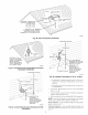
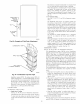
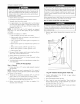

OPEN STAND "-7
PiPE FOR /
A/COR/
HUMIDIFIER j[
DRAIN
A94054
Fig. 46--Example of Field Drain Attachment
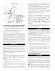
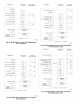
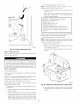
CONDENSATE
WIRE TIE(S)_ "_
HEAT TAPE_ I_
(3 WRAPS MINIMUM)_
A93036
Fig. 47--Condensate Trap Heat Tape
humidifier terminal HUM. The inducer motor IDM will
remain energized for a 15-second (040 through 120 sizes)
or 5-second (140 size) post-purge period. The blower motor
BLWM and air cleaner terminal EAC-1 will remain ener-
gized fur 90, 120, 150, or 180 seconds (depending on the
blower-OFF delay selection). The furnace control CPU is
factory-set for a 120-second blower-OFF delay.
COOLING MODE
The thermostat "calls lbr cooling."
a. Single-Speed Cooling
(See Fig. 27, 48, 50, and 52 for thermostat connections)
The thermostat closes the R to G-and-Y circuits. The R to
Y circuit starts the outdoor unit, and the R to G-and-Y.Y2
circuits start the furnace blower motor BLWM on COOL
speed.
35
The electronic air cleaner terminal EAC-1 is energized with
115 vac when the blower motor BLWM is operating.
When the thermostat is satisfied, the R to G-and-Y circuits
are opened. The outdoor unit will stop, and the furnace
blower motor BLWM will continue operating on the
COOL speed for an additional 90 seconds. Jumper Y/Y2 to
DHUM to reduce the cooling off-delay to 5 seconds. (See
Fig. 31.)
b. Two-Speed Cooling
(See Fig. 27, 49, 51, 53, and 54 tbr thermostat connec-
tions.)
The thermostat closes the R to G-and-Y1 circuits for
low-cooling or closes the R to G-and-Yl-and-Y2 circuits
for high-cooling. The R to Y1 circuit starts the outdoor unit
on low-cooling speed, and the R to G-and-Y1 circuit starts
the furnace blower motor BLWM on low-cool speed (same
speed as FAN). The R to Yl-and-Y2 circuits start the
outdoor unit on high-cooling speed, and the R to G-and-
Y/Y2 circuits start the furnace blower motor BLWM on
COOL speed.
The electronic air cleaner terminal EAC-1 is energized
with 115 vac whenever the blower motor BLWM is
operating.
When the thennostat is satisfied, the R to G and-Y1 or R to
G and-Y1 and-Y2 circuits are opened. The outdoor unit
stops, and the furnace blower BLWM and electronic air
cleaner temfinal EAC-I will remain energized for an
additional 90 seconds. Jumper Y1 to DHUM to reduce the
cooling off-delay to 5 seconds. (See Fig. 31.)
THERMIDISTAT MODE
(See Fig. 48, 49, 50, and 51 for Thermidistat connections.)
The dehumidification output, DHUM on the Thermidistat
should be connected to the furnace control thermostat temfinal
DHUM. When there is a dehumidify demand, the DHUM
input is activated, which means 24 vac signal is removed from
the DHUM input terminal. In other words, the DHUM input
logic is reversed. The DHUM input is turned ON when no
dehumidify demand exists. When 24 vac is initially detected
by the furnace control on the DHUM input, the furnace control
operates in Thennidistat mode. If the DHUM input is low or
OFF tbr more than 48 hours, the furnace control reverts back
to non-Thermidistat mode.
The cooling operation described in item 2. above also applies
to operation with a Thermidistat. The exceptions are listed
below:
a. When the R to G-and-Y1 circuit is closed and there is a
demand lbr dehumidification, the furnace blower motor
BLWM will continue running at low-cool speed (same
speed as FAN).
b. When the R to G-and Y.Y2 circuit is closed and there is a
demand for dehumidification, the fumace blower motor
BLWM will &op the blower speed from COOL to HEAT
for a maximum of 10 minutes before reverting back to
COOL speed. If there is still a demand for dehumidification
after 20 minutes, the furnace control CPU will &op the
blower speed back to HEAT speed. This alternating 10-
minute cycle will continue as long as there is a call for
cooling.
c. When the "call for cooling" is satisfied while there is a
demand for dehumidification, the cooling blower-off delay
is decreased from 90 seconds to 5 seconds.
CONTINUOUS BLOWER MODE
When the R to G circuit is closed by the thermostat, the blower
motor BLWM will operate on continuous-blower speed (can