
Operating instructions
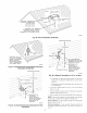
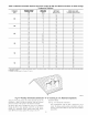
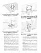
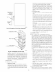
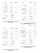
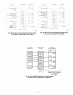
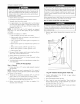

Table 8--Maximum Allowable Exposed Vent Pipe Length (It) With and Without Insulation in Winter Design
Temperature Ambient*
WINTER DESIGN MAX PIPE
FURNACE WITHOUT WITH 3/8-1N. OR
TEMPERATURE DIAMETER
SIZE (OF) (IN,) INSULATION THICKER INSULATIONt
20 ! .5 51 70
0 1.5 28 70
-20 1.5 16 70
040
20 2 45 70
0 2 22 70
-20 2 !0 58
20 2 65 70
060 0 2 35 70
-20 2 20 70
20 2 55 55
0 2 48 55
-20 2 30 55
080
20 2.5 70 70
0 2.5 47 70
-20 2.5 28 70
20 2.5 40 40
0 2.5 40 40
-20 2.5 38 40
100
20 3 70 70
0 3 50 70
-20 3 28 70
20 3 70 70
0 3 61 70
-20 3 37 70
120
20 4 70 70
0 4 48 70
-20 4 23 70
20 3 60 60
0 3 60 60
-20 3 44 60
140
20 4 70 70
0 4 57 70
-20 4 30 70
* Pipe length (ft) specified for maximum pipe lengths located in unconditioned spaces. Pipes located in unconditioned space cannot exceed total allowable pipe length
as specified in Table 7.
1 Insulation thickness based on R value of 35 per in.
A96128
Fig. 41--Rooftop Termination (Dimension "A" is Touching or 2-in. Maximum Separation)
during the 90-second period, after which the LED will be ON
continuous, as long as no faults are detected. After the 90-second
period, the fi_rnace will respond to the thermostat normally.
The blower door must be installed for power to be conducted
through the blower door interlock switch ILK to the Ii_rnace
control CPU, transIbnner TRAN, inducer motor IDM, blower
motor BLWM, hot-surface igniter HSI, and gas valve GV.
33
HEATING MODE
(See Fig. 27 for thermostat connections.)
The wall thermostat "calls for heat," closing the R to W
circuit. The furnace control performs a self-check, verifies the
pressure switch contacts PRS are open, and starts the inducer
motor IDM.