
Operating instructions
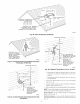
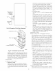
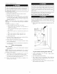

AIR AND VENT
8 3/4" FOR 3" KIT
6 3/4" FOR 2" KIT
MAINTAIN 12 IN.
CLEARANCE ABOVE HIGHEST
ANTICIPATED SNOW LEVEL.
MAXIMUM OF 24 IN. ABOVE ROOF.
A87224
Fig. 36--Roof Termination (Preferred)
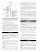
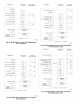
MAINTAIN 12 IN. \_
(18 IN. FOR CANADA) _N@_-_/S/_
MINIMUM CLEARANCE _>_-_/
ABOVE HIGHEST x(____/
ANTICIPATED SNOW
LEVEL. MAXIMUM OF
24 IN. ABOVE ROOF.
A93054
Fig. 37--Concentric Vent and Combustion-Air Roof
Termination (Preferred)
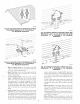
12 IN.
CLEARANCE
ABOVE HIGHEST
ANTICIPATED SNOW
LEVEL OR GRADE,
WHICHEVER IS
GREATER.
A93055
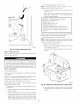
Fig. 38--Concentric Vent and Combustion-Air Side
Termination
./J Jr
IN. SEPARATION
BOTTOM OF
:'COMBUSTION AIR AND
OF VENT
/ 12 IN.
.'.-. :.." CLEARANCE
•: _ ABOVE HIGHEST
ANTICIPATED SNOW
LEVEL OR GRADE,
COMBUSTION-AIR WHICHEVER IS
GREATER.
A87225
Fig. 39_idewall Termination of 12 in. or More
d. Termination kit should be positioned where it will not be
damaged by or subjected to foreign objects, such as stones,
balls, etc.
e. Termination kit should be positioned where vent vapors are
not objectionable.
2. Cut one 4-in. diameter hole tbr 2-in. kit, or one 5-in. diameter
hole for 3-in. kit.
3. Loosely assemble concentric vent/air termination components
together using instructions in kit.
4. Slide assembled kit with rain shield REMOVED through hole.
NOTE: Do not allow insulation or other materials to accumulate
inside of pipe assembly when installing it through hole.
Roof terminations Locate assembly through roof to appropriate
height as shown in Fig. 37.
Sidewall terminations Locate assembly through sidewall with
rain shield positioned no more than l-in. from wall as shown in
Fig. 38.
31