
Operating instructions
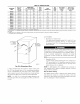

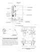


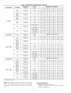
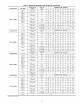

Table 7--Maximum Allowable Pipe Length (ft) (Continued)
ALTITUDE (FT)
8001 to 9000€
ALTITUDE (FT)
9001 to 10,000$
UNIT SIZE
040-08
040-!2
060-08
060-!2
060-16
080-!2
080-!6
080-20
100-16
100-20
120-20
140-20
UNIT SIZE
040-08
040-!2
060-08
060-!2
060-!6
080-!2
080-16
080-20
100-16
100-20
120-20
140-20
TERMINATION
TYPE
2 Pipe or 2-in
Concentric
2 Pipe or 2-in
Concentric
2 Pipe or 2-in
Concentric
2 Pipe or 3-in
Concentric
2 Pipe or 3-in.
Concentric
TERMINATION
TYPE
2 Pipe or 2-in
Concentric
2 Pipe or 2-in
Concentric
2 Pipe or 2-in
Concentric
2 Pipe or 3-in
Concentric
2 Pipe or 3-in.
Concentric
PIPE DIA NUMBER OF 90 ° ELBOWS
(IN.)* 1 2 3 4 5
1-1/2 46 41 36 31 29
2 62 60 58 56 55
1-1/2 11 6 NA NA NA
2 49 44 42 37 35
2 33 28 !7 !2 !0
2-!/2 62 60 58 56 55
2-!/2 23 15 7 5 NA
3 59 54 49 44 39
31- no disk 10 NA NA NA NA
41- no disk 35 30 25 20 !5
NA
PIPE DIA NUMBER OF 90 ° ELBOWS
(IN.)* 1 2 3 4 5
1-!/2 42 37 32 27 25
2 57 55 53 51 49
6
24
53
NA
34
NA
53
NA
34
NA
10
6
20
47
45 40 38 33 31 29
2 30 25 !4 9 7 NA
2-!_ 57 55 53 51 49 47
2-1/2 21 13 5 NA NA NA
3 54 49 44 39 34 29
4t no disk 10 5 NA NA NA NA
NA
Disk usage-Unless otherwise specified, use perforated disk assembty (factory-suppfied in toose parts bag). If one disk is stated, separate 2 halves of perforated disk
assembly and use shouldered disk half When using shouldered disk half, install screen side toward inlet box.
tWide radius etbow
SVent sizing for Canadian installations over 4500 ft (1370 m) above sea level are subject to acceptance by the local authorities having jurisdiction.
NA-Not Allowed; pressure switch wilt not make.
NOTES:
1 Do not use pipe size greater than those specified in tabte or incomplete combustion, flame disturbance, or flame sense Iockout may occur
2 Size both the combustion-air and vent pipe independently, then use the larger diameter for both pipes
3. Assume two 45 ° elbows equal one 90 ° elbow Long radius etbows are desirable and may be required in some cases
4 EIbows and pipe sections within the furnace casing and at the vent termination should not be included in vent length or etbow count.
5 The minimum pipe length is 5 ft for atl applications
6 Use 3-in. diameter vent termination kit for installations requiring 4-in diameter pipe.
a. Comply with all clearance requirements as stated in Table
5.
b. Termination kit should be positioned where vent vapors
will not damage plants/shrubs or air conditioning equip-
ment.
c. Termination kit should be positioned so that it will not be
affected by wind eddy (such as inside building corners) or
allow recirculation of flue gases, airborne leaves, or light
sno_,v.
d. Termination kit should be positioned where it will not be
damaged by or subjected to foreign objects, such as stones,
balls, etc.
e. Termination kit should be positioned where vent vapors are
not objectionable.
2. Cut 2 holes, 1 for each pipe, of appropriate size for pipe size
being used.
3. Loosely install elbow in bracket and place assembly on
combustion-air pipe.
Roof terminations_oosely install pipe coupling on prop-
erly cut vent pipe. Coupling must be positioned so bracket will
mount as shown in Fig. 36.
For applications using combustion-air pipe option, indicated
by dashed lines in Fig. 36, install 90 ° street elbow into 90 °
elbow, making U-fitting. A 180 ° U-fitting may be used.
SidewMl terminations Install bracket as shown in Fig. 39 or
40.
For applications using vent pipe option indicated by dashed
lines in Fig. 39, rotate vent elbow 90 ° from position shown in
Fig. 39.
4. Disassemble loose pipe fittings. (?lean and cement using same
procedures as used for system piping.
5. Check required dimensions as shown in Fig. 36, 39, or 40.
Concentric Vent/Air Termination Kit
i. Determine location for termination.
Consideration of the following should be made when deter-
mining an appropriate location for termination kit.
a. Comply with all clearance reqnirements as stated in Table
5.
b. Termination kit should be positioned where vent vapors
will not damage plants/shrubs or air conditioning equip-
ment.
c. Termination kit should be positioned so it will not be
affected by wind eddy (such as inside building comers) or
that may allow recirculation of flue gases, airborne leaves,
or light snow.
30