
Operating instructions


usedwheninstalledoncombustiblematerialsandwoodflooring.
Specialbaseisnotrequiredwhenthisfuruaceisinstalledon
manufacturer'sCoilAssemblyPartNo.CD5orCK5,orwhen(?oil
BoxPartNo.KCAKCisused.
The58MXA040through120sizeunitsareC.S.A.(AGAand
CGA)design-certifiedforuseinmanufactured(mobile)homes
whenfactoryaccessoryconversionkitisused.The140sizeunitis
NOTdesign-certifiedforuseinmanufactured(mobile)homes.
Theseli_rnacesaresuitableforinstallationinastructurebuilton
siteoramanufacturedbuildingcompletedatfinalsite.Thedesign
ofthisli_rnacelineisNOTC.S.A.design-certifiedforinstallation
inrecreationvehiclesoroutdoors.
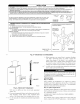
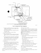
---->ThisIi_rnaceis designedfor continuousreturn-airminimum
temperatureof60OFdborintermittentoperationdownto55°Fdb
suchaswhenusedwithanightsetbackthermometer.Return-air
temperaturemustnotexceed85°Fdb.Failureto followthese
returnairlimitsmayaffectreliabilityofheatexchangers,motors
andcontrols.SeeFig.4.
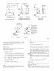
Thesefumacesareshippedwiththe&ainandpressuretubes
connectedforUPFLOWapplications.Minormodificationsare
requiredwhenusedinDOWNFLOW,HORIZONTALRIGHT,or
HORIZONTALLEFT(supply-airdischargedirection)applica-
tionsasshowninFig.1.SeedetailsinApplicationssection.
Thisfuruacemustbeinstalledwithadirect-vent(combustionair
andfluegas)systemandafactoryaccessoryterminationkit.Ina
direct-ventsystem,allairforcombustionistakendirectlyfromthe
outdooratmosphereandfluegasesaredischargedtotheoutside
atmosphere.Seefi._rnaceandfactoryaccessoryvent-airintake
terminationkitinstructionsforproperinstallation.
Thesefuruacesareshippedwiththefollowingmaterialstoassistin
properli_rnaceinstallation.Thesematerialsareshippedinthemain
blowercompartment.
Installer Packet includes:
Installation, Startup, and Operating Instructions
Service and Maintenance Instructions
User's Information Manual
Warranty Certificate
Loose Parts Bag includes: Quantity
Pressure tube extension 1
Collector Box or condensate trap extension tube 1
Inducer housing drain tube 1
1/2-in CPVC street elbow 2
Drain tube coupling 1
Drain tube coupling grommet 1
Vent and combustion-air pipe support 2
Condensate trap hole filler plug 3
Vent and combustion-air intake hole filler plug 2
Combustion-air pipe perforated disk assembly 1
Vent Pipe Extension !*
* ONLY supplied with some furnaces.
---->For accessory installation details, refer to accessory installation
instructions.
¥:I ['_Xlii][,]'/1
INTRODUCTION
The model 58MXA 4-way multipoise, Gas-Fired, Category IV,
direct-vent condensing furuace is available in model sizes ranging
in input capacities of 40,000 to 138,000 Btuh.
CODES AND STANDARDS
Follow all national and local codes and standards in addition to
these instructions. The installation must comply with regulations
of the serving gas supplier, local building, heating, plumbing, and
other codes. In absence of local codes, the installation must
comply with the national codes listed below and all authorities
having jurisdiction.
In the United States and Canada, follow all codes and standards for
the following:
Step 1--Safety
---->• US: National Fuel Gas Code (NFGC) NFPA 54-2002 ANSI
Z223.1-2002 and the Installation Standards, Warm Air Heating
and Air Conditioning Systems ANSI NFPA 90B
---->• CANADA: National Standard of Canada, Natural Gas and
Propane Installation Code (NSCNGPIC) CANiCGA -B149,1
-and.2 M-00
Step 2--General Installation
• US: NFGC and the NFPA 90B. For copies, contact the National
Fire Protection Association Inc., Batterymarch Park, Quincy,
MA 02269; or for only the NFGC contact the American Gas
Association, 400 N. Capitol, N.W., Washington DC 20001
CANADA: NSCNGPIC. For a copy, contact Standard Sales,
CSA International, 178 Rexdale Boulevard, Etobicoke (Tor-
onto), Ontario, M9W 1R3, Canada.
Step a--Combustion and Ventilation Air
• US: Section 5.3 of" the NFGC, Air for Combustion and
Ventilation
CANADA: Part 7 of the NSCNGPIC, Venting Systems and Air
Supply for Appliances
Step 4---Duct Systems
---->• US and CANADA: Air Conditioning Contractors Association
(ACCA) Manual D, Sheet Metal and Air Conditioning Con-
tractors National Association (SMACNA), or American Soci-
ety of Heating, Refrigeration, and Air Conditioning Engineers
(ASHRAE) 2001 Fundamentals Handbook Chapter 34.
Step 5--Acoustical Lining and Fibrous Glass Duct
• US and CANADA: cun'ent edition of SMACNA, NFPA 90B as
tested by UL Standard 181 for Class I Rigid Air Ducts
Step 6--Gas Piping and Gas Pipe Pressure Testing
• US: NFGC; chapters 2, 3, 4, and 9 and national plumbing codes
CANADA: NSCNGPIC Parts 3, 4, 5, A, B, E, and H.
Step 7--Electrical Connections
• US: National Electrical Code (NEC) ANSIiNFPA 70-2002
CANADA: Canadian Electrical Code CSA C22.1
ELECTROSTATIC DISCHARGE (ESD) PRECAUTIONS
Electrostatic discharge can affect electronic components.
Take precautions during fi_rnace installation and servicing to
protect the fi.lrnace electronic control. Precautions will pre-
vent electrostatic discharges fi'om personnel and hand tools
which are held during the procedure. These precautions will
help to avoid exposing the control to electrostatic discharge
by putting the fi_rnace, the control, and the person at the same
electrostatic potential.
i. Disconnect all power to the furnace. Multiple disconnects may
be required. DO NOT TOUCH THE CONTROL OR ANY
WIRE CONNECTED TO THE CONTROL PRIOR TO DIS-
CHARGING YOUR BODY'S ELECTROSTATIC CHARGE
TO GROUND.
2. Firmly touch the clean, unpainted, metal surface of the furnace
chassis which is close to the control. Tools held in a person's
hand during grounding will be satisfactorily discharged.
3. After touching the chassis, you may proceed to service the
control or connecting wires as long as you do nothing to
recharge your body with static electricity (for example; DO