
Operating instructions
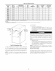

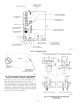

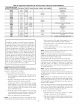

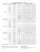
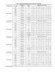

Table 6--Approved Combustion-Air and Vent Pipe, Fitting and Cement Materials
ASTM SPECIFICATION
(MARKED ON MATERIAL)
D1527
D1785
D2235
D2241
D2466
D2468
D2564
D2661
D2665
MATERIAL PIPE FITTINGS
ABS Pipe --
PVC Pipe --
For ABS -- --
PVC Pipe --
PVC -- Fittings
ABS -- Fittings
For PVC -- --
ABS Pipe Fittings
PVC Pipe Fittings
SOLVENT CEMENT AND PRIMERS
Solvent
Cement
Solvent
Cement
DESCRIPTION
Schedule-40
Schedule-40
For ABS
SDR-21 & SDR-26
Schedule-40
Schedule-40
For PVC
DWV at Schedule-40 IPS sizes
DWV
F438
F441
F442
F493
F628
F656
F891
CPVC -- Fittings
CPVC Pipe --
CPVC Pipe --
For CPVC -- --
ABS Pipe --
For PVC -- --
PVC Pipe --
m
m
m
Solvent
Cement
Primer
Schedule-40
Schedule-40
SDR
For CPVC
Cellular Core DWV at Schedule-40 IPS sizes
For PVC
Cellular Core Schedule-40 & DWV
EXAMPLE: An 080-12 size fumace located in Indianapo-
lis, elevation 650 ft above sea level, could be installed in an
application requiring 3 elbows and 32 ft of vent pipe, along
with 5 elbows and 34 ft of combustion-air pipe. Table 7
indicates this application would allow a 2-in. diameter vent
pipe, but require a 2-1/2 in. diameter combustion air pipe
(2-in. pipe is good for 35 ft with 3 elbows, but only 30 ft
with 5 elbows). Therefore, 2-1/2 in. diameter pipe must be
used for both vent and combustion-air pipes since larger
required diameter must ahvays be used for both pipes. If
same installation were in Albuquerque, elevation 5250 ft
above sea level, installation would require 2-1/2 in. vent
pipe and combustion-air pipe. At 5001- to 6000-ft eleva-
tion, 2-in. pipe is only good for 17 ft with 5 elbows, and
2-1/2 in. pipe is good for 70 ft with 5 elbows.
Combustion-Air and Vent Pipe Attachment
NOTE: All pipe joints must be cemented except attachment of
combustion-air pipe to inlet housing connection, since it may be
necessary to remove pipe for servicing.
i. Attach combustion-air pipe as follows:
a. Determine location of combustion-air intake pipe connec-
tion to combustion-air intake housing as shown in Fig. 33
for application.
b. Reposition combustion-air intake housing plug fitting in
appropriate unused intake housing connection.
c. If required per Table 7, insert perforated disk assembly
(factory-supplied in loose parts bag) in intake housing
where combustion-air intake pipe will be connected. If half
disk set is required, install with shoulder of disk against
stop in combustion-air inlet.
d. Install pipe support (lhctory-supplied in loose parts bag)
into selected furuace casing combustion-air pipe hole. Pipe
support should be positioned at bottom of casing hole.
e. Insert 2-in. diameter pipe into intake housing.
NOTE: A 2-in. diameter pipe must be used within the furnace
casing. Make all pipe diameter transitions outside furuace casing.
26
f. Install casing hole filler plug (_actory-supplied in loose
parts bag) in unused combustion-air pipe casing hole.
g. Drill a 1/8-in. hole in 2-in. combustion-air pipe using hole
in intake housing as a guide.
h. Install a field-supplied No. 6 or No. 8 sheet metal screw
into combustion-air pipe.
NOTE: DO NOT OVERTIGHTEN SCREW. Breakage of intake
housing or fitting may cause air leakage to occur.
NOTE: Do not attach combustion-air intake pipe permanently to
combustion-air intake housing since it may be necessary to remove
pipe for service of ignitor or flame sensor.
COMBUSTION-AIR INTAKE HOUSING PLUG FITTING
The combustion-air intake plug fitting must be installed in unused
combustion-air intake housing. This fitting nmst be attached by
using RTV sealant, or by drilling a 1/8-in. hole in fitting, using
hole in intake housing as a guide. Install a field-supplied No. 6 or
No. 8 sheet metal screw.
NOTE: DO NOT OVERTIGHTEN SCREW. Breakage of intake
housing or fitting may cause air leakage to occur.
A plugged &ain connection has been provided on this fitting for
use when moisture is found in combustion-air intake pipe and
combustion box.
NOTE: Moisture in combustion-air intake may be result of
improper termination. Ensure combustion-air intake pipe termina-
tion is similar to that shown in Fig. 36, 37, 38, 39, and 40 so it will
not be susceptible to areas where light snow or other sources of
moisture could be pulled in.
If use of this drain connection is desired, drill out fitting's tap plug
with a 3/16-in. &ill and connect a field-supplied 3/8-in. robe. This
tube should be routed to open condensate &ain for furuace and
AiC (if used), and should be trapped. (See Fig. 35.)
2. Attach vent pipe to furnace as follows:
a. Determine location of vent pipe connection to inducer
housing as shown in Fig. 33 for application.
b. Reposition elastomeric (rubber) inducer housing outlet cap
and clmnp to appropriate unused inducer housing connec-
tion. Tighten clamp.