
Operating instructions

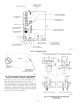


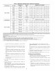

VENT
HORIZONTAL TO ROOF HORIZONTAL TO SIDEWALL
COMBUSTION-AIR PiPE
F VENT PIPE __ _ _-_='_
VERTICALTO ROOF VERTICAL TO SIDEWALL
NOTE: A 12 In. minimum offset pipe section is recommended with
short (5 to 8 ft) vent systems. This recommendation is to reduce
excessive condensate droplets from exiting the vent pipe.
Fig. 34_Short Vent (5 to 8 Ft) System
A96230
r_ |, I'-I,1, IE1}_
When vent pipe is exposed to temperatures below fi'eezing,
such as when it passes through an unheated space or when a
chimney is used as a raceway, pipe must be insulated as
shown in Table 8 with Armaflex-type insulation.
Combustion air must not be taken from inside structure
because inside air is frequently contaminated by halogens,
which include fluorides, chlorides, bromides, and iodides.
These elements are l'ound in aerosols, detergents, bleaches,
cleaning solvents, salts, air fresheners, adhesives, paint, and
other household products. Locate combustion-air inlet as far
as possible fi'om swimming pool and swimming pool pump
house.
Excessive exposure to contaminated combustion air will
result in safety and performance related problems.
Solvent cements are combustible. Keep away fi'om heat,
sparks, and open flame. Use only in well-ventilated areas.
Avoid breathing in vapor or allowing contact with skin or
eyes. Failure to follow this warning could result in fire,
property damage, personal injury, or death.
All combustion-air and vent pipes must be airtight and
watertight. Pipes must also terminate exactly as shown in Fig.
36, 37, 38, 39, or 40. Failure to follow this warning could
result in property damage, personal injury, or death.
NOTE: The minimum combustion-air and vent pipe length (each)
for these furnaces is 5 ft. Short pipe lengths (5-8 if) may discharge
water droplets. These droplets may be undesirable, and a 12-in.
mininmm of£set pipe section is recommended, as shown in Fig. 34,
to reduce excessive droplets from exiting vent pipe outlet.
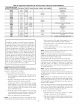
Combustion-Air and Vent Pipe Diameter
Determine combustion-air and vent pipe diameter.
i. Using Table 7, individually determine the smallest
combustion-air and vent pipe diameters permitted for each
pipe. Pick the larger of these 2 pipe diameters and use this
diameter for both combustion-air and vent pipes.
2. When installing vent systems of short pipe length, use the
smallest allowable pipe diameter. Do not use pipe size greater
than required becuase incomplete combustion, flame distur-
bance, or flame sense lockout may occur.
NOTE: Do not count elbows or pipe sections in terminations or
within fl_rnace. See shaded areas in Fig. 36, 37, 38, 39, and 40.
25