
Operating instructions


TWINNING AND/OR
BLOWER OFF-DELAY COMPONENT TEST
TERMINAL
24-V THERMOSTAT
TERMINALS
3-AMP FUSE
LED
DIAGNOSTIC LIGHT
115-VAC(L2)I
CONNECTIONS
HUMIDIFIER TERMINAL
(24-VAC 0.5 AMP MAX.)
TRANSFORMER 24-VAC
CONNECTIONS
ob
PL1 -LOW VOLTAGE MAIN
HARNESS CONNECTOR
13[-I
_ SPARE/-1 //_Of t "_ \
/ _ _ 115 VAC (L1) LINE PL2-HOT SURFACE
J__ SPARE-2 FAN _ VOLTAGE CONNECTION IGNITER & INDUCER
SEL O,W 4 t A S\ / \ MOTORCONNBOTOR
/ EAC-1 TERMINAL
(115-VAC 10 AMP MAX)
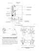
Fig. 31--Furnace Control
A02142
NOT IN
HORIZONTAL
SECTION
• FURNACE • _i
TRANSITION IN
VERTICAL SECTION
A93034
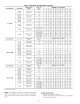
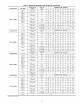
Fig. 32--Combustion-Air and Vent Pipe Diameter
Transition Location and Elbow Configuration
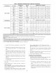
Each furnace must have its own set of" combustion-air and vent
pipes and be terminated individually, as shown in Fig. 42.
Other gas appliances with their own venting system may also use
the abandoned chinmey as a raceway providing it is pennitted by
local code, the NFGC or NSCNGPIC, and the vent or liner
manufacturer's installation instructions. Care must be taken to
prevent the exhaust gases from one appliance from contaminating
the combustion air of other gas appliances.
NOTE: Select 1 vent pipe connection and
1 combustion-air pipe connection
AIR
COMBUSTION-AIR _ COMBUSTION-AIR
UPFLOW
COMBUSTION-
AIR
VENT
HORIZONTAL-LEFT DISCHARGE
NOTE: Select 1 vent pipe connection and
1 combustion-air pipe connection
COMBUSTION- _ COMBUSTION-
AIR AIR AIR
FLOW
DOWNFLOW
COMBUSTION-
AIR
VENT
HORIZONTAL-RIGHT DISCHARGE
A96187
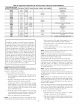
Fig. 33--Combustion-Air and Vent Pipe
Connections
24