
Operating instructions


REMOVAL OF EXISTING FURNACES FROM COMMON
VENT SYSTEMS
---) When an existing Category I furnace is removed or replaced, the
original venting system may no longer be sized to properly vent
the remaining attached appliances. An improperly sized Category
I venting system could cause the formation of condensate in the
furnace and vent, leakage of condensate and combustion products,
and spillage of combustion products into the living space, etc.
¥!_ _I_UH _[_
CARBON MONOXIDE POISONING HAZARD
Failure to ]`bllow the steps outlined below lbr each appliance
connected to the venting system being placed into operation
could result in carbon monoxide poisoning or death.
The following steps shall be followed ].'or each appliance
connected to the venting system being placed into operation,
while all other appliances connected to the venting system are
not in operation:
1. Seal any unused openings in venting system.
2. Inspect the venting system for proper size and horizontal
pitch, as required in the National Fuel Gas (?ode, ANSI
Z223.1'NFPA 54 or the CSA B149.1, Natural Gas and
Propane Installation (?ode and these instructions. Deter-
mine that there is no blockage or restriction, leakage,
corrosion and other deficiencies, which could cause an
unsafe condition.
3. As far as practical, close all building doors and windows
and all doors between the space in which the appli-
ance(s) connected to the venting system are located and
other spaces of the building.
4. Close fireplace dampers.
5. Tnrn on clothes dryers and any appliance not connected
to the venting system. Turu on any exhaust fans, such as
range hoods and bathroom exhausts, so they are operat-
ing at maximum speed. Do not operate a summer
exhaust fan.
6. Follow the lighting instructions. Place the appliance
being inspected into operation. Adjust the thermostat so
appliance is operating continuously.
7. Test ]`'or spillage from draft hood equipped appliances at
the draR hood relief opening aRer 5 minutes of main
buruer operation. Use the flame of a match or candle.
8. If improper venting is observed during any of the above
tests, the venting system must be corrected in accordance
with the National Fuel Gas Code, ANSI Z223.1.NFPA
54 and/or CSA B149.1, Natural Gas and Propane Instal-
lation (?odes.
9. After it has been determined that each appliance con-
nected to the venting system properly vents when tested
as outlined above, returu doors, windows, exhaust rims,
fireplace dampers and any other gas-fired buruing appli-
ance to their previous conditions of use.
Vent system or vent connectors may need to be resized. For any
other appliances when resizing vent systems or vent connectors,
system or connector must be sized to approach mininmm size as
determined using appropriate table found in the NFGC or NSC-
NGPIC.
In Canada construct all combustion-air and vent pipes for this
fi_rnace of CSA or ULC listed schedule-40 PVC, PVC-DWV or
ABS-DWV pipe and pipe cement. SDR pipe is NOT approved in
Canada.
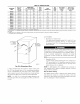
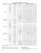
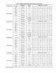
See Table 7 for maximum pipe lengths and Fig. 36, 37, 38, 39, and
40 for exterior piping arrangements.
NOTI=: Furuace combustion-air and vent pipe connections are
sized ]`'or 2-in. pipe. Any pipe size change should be made outside
fi_rnace casing in vertical pipe. (See Fig. 32.) This allows proper
drainage of vent condensate.
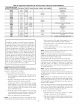
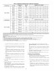
Combustion-air and vent pipes must terminate together in same
atmospheric pressure zone, either through roof or sidewall (roof
termination preferred), using accessory termination kit. See Table
5 l'or required clearances.
___>
Table 5--Combustion-Air and Vent Pipe
Termination Clearances
CLEARANCE (FT)
USA
1
See Note 5
3
See Note 4
LOCATION
Canada
Above grade level or above 11-
anticipated snow depth
Dryer/Water heater vent See Note 5
From plumbing vent stack 3
From any mechanical fresh air intake See Note 6
For furnaces with an input capacity of
100,000 Btuh or less--from any non-
mechanical air supply (windows or doors 1 1
which can be opened) or combustion-air
opening
For furnaces with an input capacity greater
than 100,000 Btuh --from any non-
mechanical air supply (windows or doors 1 3
which can be opened) or combustion-air
opening
From service regulator vent, electric and
See Note 6 See Note 6
gas meters and relief equipment
Above grade when adjacent to public See Note 3 See Note 3
walkway
1 18 in. above roof surface in Canada
NOTES:
1. If installing 2 adjacent furnaces, refer to Multiventing and Vent Terminations
section for proper vent configurations.
2. When locating combustion-air and vent terminations, consideration must be
given to prevailing winds, location, and other conditions which may cause
recirculation of the appliance's own flue products or the flue products of
adjacent vents Recirculation can cause poor combustion, inlet condensate
problems, and accelerated corrosion of heat exchangers.
3. Vent termination can not terminate tess than 2 ft horizontal and 7 ft above
public walkway or where condensate vapor or droplets may be a hazard.
4. Vent termination must be at least 3 feet above any forced draft inlets within
10 feet horizontal. Vent termination must be at least 3 feet horizontal from
other direct vent appliances intake unless otherwise specified by manufac-
turer
5. 3 ft radius of furnace vent air-intake terminal and 1 ft horizontally from
vertical centerline of furnace vent air-intake terminaI.
6. Above a meter/regulator within 3 feet horizontally of vertical centerline of
meter/regulator vent outlet to a maximum vertical distance of 15 feet
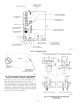
Furnace combustion-air and vent pipe connections nmst be at-
tached as shown in Fig. 33. Combustion-air intake plug fitting and
inducer housing alteruate vent cap may need to be relocated in
some applications.
NOTI=: Slope combustion-air and vent pipes downwared toward
fi_rnace a mininmm of i/4 in. per linear ft with no sags between
hangers.
COMBUSTION-AIR AND VENT PIPING
General
Combustion-air and vent pipe, fittings, primers, and solvents must
con]`'orm to American National Standards Institute (ANSI) stan-
dards and American Society ]`'or Testing and Materials (ASTM)
standards. See Table 6 ]`br approved materials ]`br use in the U.S.A.
An abandoned masonry chimney may be used as a raceway for
properly insulated and supported combustion-air and vent pipes.
23