
Operating instructions


FURNACE
SIZE
040-08
040-12
060-08
060-12
060-16
080-12
080-16
080-20
100-t6
100-20
120-20
140-20
VOLTS--
HERTZ--
PHASE
115-80-1
115-60-1
115-80-1
115-60-1
115-80-1
115-60-1
115-80-1
115-60-1
115-80-1
115-60-1
115-80-1
115-60-1
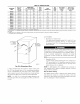
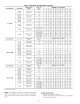
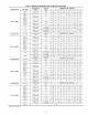
Table 4_Electrical Data
OPERATING
VOLTAGE RANGE
Max* Min*
127 104
127 104
127 104
127 104
127 104
127 104
127 104
127 104
127 104
127 104
127 104
127 104
MAX
UNIT
UNIT
AMPS AMPACITYI"
6.1 8.4
7.3 10.0
6.1 8.4
7.1 9.8
9.5 12.8
7.6 10.4
!0.0 13.4
14.1 18.4
!0.2 13.5
!4.8 19.3
!4.6 19.!
14.3 18.8
MIN
WIRE
SIZE
14
14
14
14
14
14
14
12
14
12
12
12
MAX WIRE
LENGTH
(FT):_
44
37
44
38
29
36
28
31
27
3O
3O
3O
* Permissible limits of voltage range at which unit will operate satisfactorily.
MAX FUSE
OR CKT BKR
AMPS**
15
15
15
15
15
15
15
2O
15
2O
20
20
1 Unit ampacity = 125 percent of largest operating component's full load amps plus 1O0 percent of all other potentiaI operating components' (EAC, humidifier, etc.) full
load amps
$ Length shown is a measured way along wire path between unit and service panel for maximum 2 percent voItage drop.
** Time-delay type is recommended.
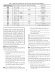
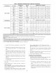
ALTERNATE
FIELD
LOCATION
S ACTORY
INSTALLED
LOCATION
A00212
Fig. 29--Relocating J-Box
a 3-amp, automotive-type fuse located on furuace control. (See
Fig. 31.) Any electrical shorts of 24-v wiring during installation,
service, or maintenance may cause fuse to blow. If fuse replace-
ment is required, use only a fuse of identical size (3 amp) and type.
The control will flash code 24 when fuse needs replacement.
NOTE: Use AWG No. 18 color-coded copper thermostat wire
for lengths up to 100 ft. For wire lengths over I00 ft, use AWG No.
16 wire.
ACCESSORIES
i. Electronic Air (;leaner (EAC)
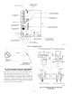
Two quick-connect terminals marked EAC-1 and EAC-2 are
provided for EAC connection. (See Fig. 31.) These temfinals
arc energized with 115-v (1.0-amp maximum) during blower
motor operation.
DO NOT connect furuace control HUM terminal to HUM
(humidifier) terminal on Thermidistat TM, Zone Controller or
similar device. See Thennidistat TM, Zone Controller, thermo-
stat, or controller manufacturer's instructions for proper
connection. A failure to follow this warning could result in
fire.
2. Humidifier (HUM)
A quick-connect terminal (HUM) and screw terminal (CoM
24V) are provided for 24-v humidifier connection. (See Fig.
30.) HUM terminal is energized with 24-v (0.5-amp maxi-
nmm) when gas valve is energized.
NOTI=: A field-supplied, l15-v controlled relay connected to
EAC terminals may be added if humidifier operation is desired
during all blower operation.
Step 9--Direct Venting
The 58MXA furnaces require a dedicated (one 58MXA furnace
only) direct-vent system. In a direct-vent system, all air for
combustion is taken directly fi'om outdoor atmosphere, and all flue
gases are discharged to outdoor atmosphere.
21