
Operating instructions


.... FIELD 24-V WIRING
.... FIELD !15-, 208/230-, 460-V WIRING
-- FACTORY 24-V WIRING
FACTORY 1! 5-V WI RING
NOTE21_ #Am%m _ _ I THERMOSTAT
FIVEWIRE_ ILZyLyJL?J _ L4JI TERMINALS FIELD-SUPPLIED
THREE-WIRE _ '_ _ i_' DISCONNECT
HEATING-ONLY "--_"_1 _._ 11 I I _ ._
'(--L_
w .....
I I _ ................ 208/230- OR1
BLOWER DOOR SWITCH --x -- ,L_ '
\. _ I I .... -_, 460-V
--,---- _ _ i .I"THREE
• E 1 I 1 I --....
BLKI_I BLI, _ ? _-- I I I j PHASE
._ i , , , .....
_...________ .._ i 51_L_._ c .... I--" ', ', .........................................
WHT H @ I I
--J--..---I....o I NI 1 1 ', I H--_[]3]_,I---]208/230-V
I =_,,,_ I rf_ GNDI TI _ 4 I I r',- I..... I___b_l / S NGLE
I I I FI It-,,DL--
115-VFIELD-AUXILIARY /--- ,, {/ ,,----q---,---I---J
SUPPLIED J-BOX Elco_ .... -N-_q:_ _--- _ Ii tl_
DISCONNECT I_- _ _ CONDENSING
24-V _ TWO
TERMINAL WIRE
BLOCK
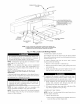
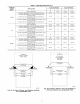
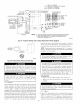
FURNACE NOTES: 1. Connect Y-terminal in furnace as shown for proper blower operation.
2. Some thermostats require a "C" terminal connection as shown.
3. If any of the original wire, as supplied, must be replaced, use
same type or equivalent wire.
A99440
Fig. 27--Typical Heating and Cooling Application Wiring Diagram
ELECTRIC
DISCONNECT
SWITCH
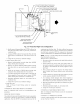
properly sized fuse or circuit breaker for this furnace. See Table 4
for wire size and fuse specifications. A disconnecting means must
be located within sight from and readily accessible to furnace.
NOTI=: Proper polarity must be maintained for 115-v wiring. If
polarity is incorrect, control LED status indicator will flash rapidly
and furnace will NOT operate.
®
A93033
Fig. 28--Disconnect Switch and Furnace
¥:I i'J#'_l1:1,"!t2[__
¥.'I |"1_'I ;t ,'I[_[__
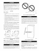
Blower access door switch opens 115-v power to control. No
component operation can occur. Do not bypass or close
switch with panel removed. Failure to follow this warning
could result in personal injury or death.
_ [qZIliiIgn
Furnace control must be grounded for proper operation or
control will lock out. Control is grounded through
green/yellow wire connected to gas valve and burner box
screwY.
i15 V WIRING
Before proceeding with electrical connections, make certain that
voltage, frequency, and phase correspond to that specified on
furnace rating plate. Also, check to be sure that sen,ice provided
by power supply is sufficient to handle load imposed by this
equipment. Refer to rating plate or Table 4 for equipment electrical
specifications. Make all electrical connections in accordance with
National Electrical Code (NEC) ANSI_NFPA 70-2002 and any
local codes or ordinances that might apply. For Canadian instal-
lations, all electrical connections must be made in accordance with
Canadian Electrical Code CSA C22.1 or authorities having juris-
diction. Use a separate, branch electrical circuit containing a
The cabinet MUST have an uninten'upted or unbroken ground
according to NEC ANSI, NFPA 70-2002 and Canadian Elec-
trical Code CSA C22.1 or local codes to minimize personal
injury if an electrical fault should occur. This may consist of
electrical wire or conduit approved for electrical ground when
installed in accordance with existing electrical codes. Do not
use gas piping as an electrical ground. Failure to lbllow this
warning could result in electrical shock, fire, or death.
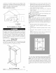
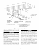
J-Box Relocation
i. Remove 2 screws holding auxiliary J-box. (See Fig. 29.)
2. Rotate J-box 180 ° and attach box to left side, using holes
provided.
¥:I [_']T!
If manual disconnect switch is to be mounted on furnace,
select a location where a drill or fastener will not contact
electrical or gas components.
24V WIRING
---->Connect 24-v thermostat leads to 24-v terminal block on furnace
control. For proper cooling operation, Y wire lYom thermostat
MUST be connected to Y/Y2 terminal on furnace control, as
shown in Fig. 27. The 24-v terminal block is marked for easy
connection of field wiring. (See Fig. 30.) The 24-v circuit contains
20