
Operating instructions
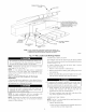
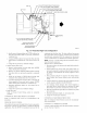
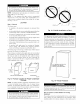
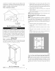
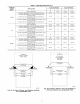

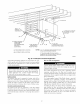

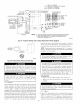

Table 3--Maximum Capacity of Pipe*
NOMINAL
IRON
PIPE
SIZE
(IN,)
1/2
3/4
1
1-1/4
1-1/2
INTERNAL
DIAMETER
(IN,)
0.622
0.824
1.049
1.380
1.610
LENGTH OF PIPE (FT)
10 20 30 40 50
175 120 97 82 73
360 250 200 170 151
680 465 375 320 285
1400 950 770 660 580
2100 !460 1180 990 900
* Cubic ft of gas per hr for gas pressures of 0.5 psig (14Mn wc) or less and a
pressure drop of 0.5-in wc (based on a 0.60 specific gravity gas).
Ref: Table 9.2 NFGC.
meter. Support all gas piping with appropriate straps, hangers, etc.
Use a minimum of 1 hanger every 6 ft. Joint compound (pipe dope)
should be applied sparingly and only to male threads of joints. Pipe
dope must be resistant to propane gas.
GAS
SUPPLY
MANUAL _/ II
vsA" J°FF
/REOU,REOpt
A93324
Fig. 2g--Typical Gas Pipe Arrangement
Connect gas pipe to furnace using a backup wrench to avoid
damaging gas controls.
"_lfl/llH .,-1
Gas valve shutoff switch MUST be facing forward or tilted
upward. Failure to follow this warning could result in
property damage or death.
Never purge a gas line into a combustion chamber. Never test
for gas leaks with an open flame. Use a commercially
available soap solution made specifically for the detection of
leaks to check all connections. A failure to follow this
warning could result in fire, explosion, personal il!iury, or
death.
Use proper length of pipe to avoid stress on gas control
manifold. Failure to follow this warning could result in a gas
leak resulting in fire, explosion, personal il!iury, or death.
Install a sediment trap in riser leading to furnace. Trap can be
installed by connecting a tee to riser leading to furnace so
straight-through section of tee is vertical. Then connect a capped
nipple into lower end of tee. Capped nipple should extend below
level of gas controls. Place a ground joint union between gas
control manifold and manual gas shutoff valve. (See Fig. 26.)
If a flexible connector is required or allowed by authority
having jurisdiction, black iron pipe shall be installed at
furnace gas control valve and extend a minimum of 2 in.
outside furnace casing.
If local codes allow the use of a flexible gas appliance connector,
always use a new listed connector. Do not use a connector which
has previously served another gas appliance.
FIRE OR EXPLOSION HAZARD
Failure to follow the safety warnings exactly could result in
serious injury, death or property damage.
Never test for gas leaks with an open flame. Use a commer-
cially available soap solution made specifically for the
detection of leaks to check all connections. A fire or explo-
sion may result causing property damage, personal injury or
loss of life.
---->An accessible manual shutoff valve MUST be installed external to
furnace casing and within 6 ft of furnace. A Ii8-in. NPT plugged
tapping, accessible for test gage connection, MUST be installed
immediately upstream of gas supply connection to furnace and
downstream of manual shutoff valve.
NOTE: The gas valve inlet pressure tap connection is suitable to
use as test gage connection providing test pressure DOES NOT
exceed maximum 0.5 psig (14-in. wc) stated on gas control valve.
(See Fig. 57.)
Piping should be pressure and leak tested in accordance with
NFGC in the United States or NSCNGPIC in Canada, local, and
national plumbing and gas codes before the furnace has been
connected. After all connections have been made, purge lines and
check for leakage at furnace prior to operating furnace.
If pressure exceeds 0.5 psig (14-in. wc), gas supply pipe must be
disconnected from furnace and capped before pressure test. If test
pressure is equal to or less than 0.5 psig (14-in. wc), turn off
electric shutoff switch located on furnace gas control valve and
accessible manual shutoff valve before test. After all connections
have been made, purge lines and check for leakage.
---->The gas supply pressure shall be within the maximum and
minimum inlet supply pressures marked on the rating plate with
the furnace burners ON and OFF.
Step 8--Electrical Connections
See Fig. 27 for field wiring diagram showing typical field 115-','
and 24-v wiring. Check all _actory and field electrical connections
for tightness.
---->Field-supplied wiring shall conform with the limitations of 63°F
(33°C)rise.
19