
Operating instructions
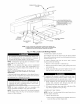
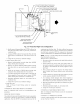
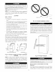
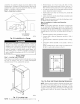
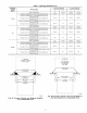

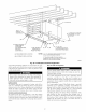

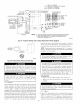

Table 2--Filter Information
AIR FILTER LOCATED IN BLOWER COMPARTMENT
FURNACE FILTER SIZE (IN.) FILTER
CASING
WIDTH (IN.) Side Return Bottom Return TYPE
17-1/2 (1) 16 X 25 X 11- (1) 16 X 25 X 1! Cleanable
21 (1) 16X25Xl* (1) 20X25X !1" Cleanable
24-1/2 (1 or 2) !6X25X1* (1) 24X25X 11" Cleanable
* Filters may be field modified by cutting filter material and support rods (3) in
fitters. Alternate sizes and additional filters may be ordered from your dealer
1-Factory-provided with furnace.
Use care when cutting support rods in filters to protect against
flying pieces and sharp rod ends. Wear safety glasses, gloves,
and appropriate protective clothing. Failure to follow this
caution could result in personal iniury.
171/2-1N.WIDE
CASINGS ONLY:
INSTALL FIELD-SUPPLIED
FILTER FILLER STRIP
UNDER FILTER.
_Z_Z22 .................
r:! [ '%lliilI'lll
For airflow requirements above 1800 CFM, see Air Delivery
table in Product Data literature for specific use of single side
inlets. The use of both side inlets, a combination of 1 side and
the bottom, or the bottom only will ensure adequate return air
openings for airflow requirements above 1800 CFM.
NOTE: Side return-air openings can ONLY be used in UPFLOW
configurations. Install filter(s) as shown in Fig. 23. Bottom
return-air opening may be used with all 4 orientations. Filter may
need to be cut to fit some furnace widths. Install filter as shown in
Fig. 24.
RETAINER
\
A93045
Fig. 23--Filter Installed for Side Inlet
NOTE: Remove and discard bottom closure panel when bottom
inlet is used.
Step G--Bottom Closure Panel
These furnaces are shipped with bottom enclosure panel installed
in bottom return-air opening. This panel MUST be in place when
side return air is used.
To remove bottom closure panel, perfoml following:
i. Tilt or raise furnace and remove 2 screws holding front filler
panel. (See Fig. 25.)
2. Rotate front filler panel downward to release holding tabs.
3. Remove bottom closure panel.
4. Reinstall front filler panel and screws.
FILTER
\
\ FILTER
RETAINER
SUPPORT
Fig. 24_Bottom Filter Arrangement
A00213
18
I
I
I
BOTTOM
CLOSURE
PANEL
FRONT FILLER
PANEL
A93047
Fig. 25--Removing Bottom Closure Panel
Step 7--Gas Piping
Gas piping nmst be installed in accordance with national and local
codes. Refer to cun'ent edition of NFGC in the United States.
Canadian installations must be made in accordance with NSCNG-
PIC and all authorities having jurisdiction.
Gas supply line should be a separate line running directly from
meter to furnace, if possible. Refer to Table 3 for recommended
gas pipe sizing. Risers nmst be used to connect to furnace and to