
Operating instructions


ANGLE
IRON OR
EQ
(B)
(A) ROD LOCATION
USING DIMPLE
LOCATORS
(SEE DIMENSIONAL
DWG FOR
LOCATIONS)
3/8-1N.
& WASHER (4)
REQD PER ROD
II
II
II
II
3/8-1N.ROD
ALTERNATE SUPPORT
LOCATION 4-IN. MIN
8-IN. MAX
_) (I_-INI MAX
(B) ALTERNATE SUPPORT
LOCATION FROM BACK
(A) PREFERRED ROD LOCATION
(B) ALTERNATE ROD LOCATION
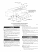
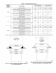
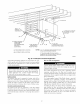
NOTES: 1. A 1 In. clearance minimum between top of
furnace and combustible material.
2. The entire length of furnace must be
supported when furnace is used in horizontal
position to ensure proper drainage.
A93304
Fig. 22--Crawlspace Horizontal Application
with another fuelibuming appliance not of the directivent type,
shall be operable only when any door or panel covering an opening
in the furnace fan compartment or in a return air plenum on ducts
is in the closed position.
¥.'I WI-I_t_II _['-1
Never connect return-air ducts to the back of the furnace.
Return-air duct connections on furnace side(s) permitted in
upflow applications only. A failure to follow this warning
could result in fire, personal il_iury, or death.
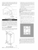
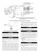
Upflow Furnaces
The return-air duct must be connected to bottom, sides (left or
right), or a combination of bottom and side(s) of main furnace
casing as shown in Fig. 2 Bypass humidifier may be attached into
unused side return air portion of the furnace casing. DO NOT
connect any portion of return-air duct to back of furnace casing.
Downflow and Horizontal Furnaces
The return-air duct must be connected to end inlet opening
provided as shown in Fig. 2. DO NOT cut into casing sides or back
to attach any portion of return-air duct. Bypass humidifier connec-
tions should be made at ductwork or coil casing sides exterior to
furnace.
Step 5iFilter Arrangement
Never operate furnace without a filter or with filter access
door removed. Failure to follow this warning can cause fire,
personal il_iury, or death
The air filter arrangement will vary due to application, furnace
orientation, and filter type. The filter may be installed in an
external Filter'Media cabinet (if provided) or the furnace blower
compartment. Factory supplied washable filters are shipped in the
blower compartment.
If a factory-supplied external Filter.Media cabinet is provided,
instructions for its application, assembly, and installation are
packaged with the cabinet. The Filter/Media cabinet can be used
with the factory-supplied washable filter or a factory-specified
high-efficiency disposable filter (see cabinet instructions).
If installing the filter in the furnace blower compartment, deter-
mine location for filter and relocate filter retaining wire, if
necessary. See Table 2 to determine correct filter size for desired
filter location. Table 2 indicates filter size, location, and quantity
shipped with this furnace. See Fig. 2 lbr location and size of
bottom and side return-air openings.
17