
Operating instructions
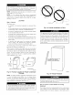


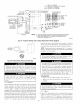

Do not bend duct flanges inward as shown in Fig. 21. This
will affect airflow across heat exchangers and may cause limit
cycling or premature heat exchanger failure. Remove duct
flange completely or bend it inward a minimum of 210 ° as
shown in Fig. 21.
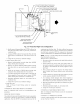
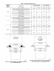
NOTE: For 140 size unit when installed in downflow orientation,
cut the white jumper wire offbetween terminals PLI-7 and PL1-9.
Do not cut white jumper between terminals PL1-7 and PLI-I1.
Refer to Fig. 30 for location of jumper. Cut jumper close to
connector and remove wire to avoid a short circuit.
Step 3--Installation in Horizontal Applications
r.,l [,-72111iI_jN
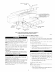
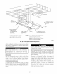
The entire length of furnace MUST be supported when
furnace is used in a horizontal position to ensure proper
draining. When suspended, bottom brace supports sides and
center blower shelf. When unit is supported from the ground,
blocks or pad should support sides and center blower shelf
area.
These furnaces can be installed horizontally in either horizontal
left or right discharge position. In a crawlspace, furnace can either
be hung fi'om floor joist or installed on suitable blocks or pad.
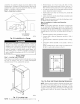
Furnace can be suspended from each comer by hanger bolts and
angle iron supports. (See Fig. 22.) Cut hanger bolts (4 each 3/8-in.
all-thread rod) to desired length. Use 1 X 3/8-in. flat washers,
3/8-in. lock washers, and 3/8-in. nuts on hanger rods as shown in
Fig. 22. Dimples are provided for hole locations. (See Fig. 2.)
DISCHARGE DUCT
FLANGE
Y
210°
MIN
NO
YES
YES
Ag302g
Fig. 21--Duct Flanges
Step 4--Air Ducts
GENERAL REQUIREMENTS
The duct system should be designed and sized according to
accepted national standards such as those published by: Air
Conditioning Contractors Association (ACCA), Sheet Metal and
Air Conditioning Contractors National Association (SMACNA) or
American Society of Heating, Refrigerating and Air Conditioning
Engineers (ASHRAE) or consult The Air 5_'stems Design Gz_ide-
lines reference tables available from your local distributor. The
duct system should be sized to handle the required system design
CFM at the design static pressure.
16
When a furnace is installed so that the supply ducts carry air
circulated by the furnace to areas outside the space containing the
furnace, the return air shall also be handled by a duct(s) sealed to
the furnace casing and terminating outside the space containing the
furnace.
Secure ductwork with proper fasteners for type of ductwork used.
Seal supply- and return-duct connections to furnace with code
approved tape or duct sealer.
Flexible connections should be used between ductwork and
furnace to prevent transmission of vibration. Ductwork passing
through unconditioned space should be insulated to enhance
system performance. When air conditioning is used, a vapor
ban'ier is recommended.
Maintain a 1-in. clearance from combustible materials to supply air
ductwork for a distance of 36-in. horizontally from the fumace.
See NFPA 90B or local code for further requirements.
For a furnace not equipped with a cooling coil, the outlet duct shall
be provided with a removable access panel. This opening shall be
accessible when the furnace is installed and shall be of such a size
that the heat exchanger can be viewed for possible openings using
light assistance or a probe can be inserted for sampling the air
stream. The cover attachment shall prevent leaks.
DUCTWORK ACOUSTICAL TREATMENT
Metal duct systems that do not have a 90 degree elbow and 10 ft
of main duct to the first branch take-off may require internal
acoustical lining. As an altemative, fibrous ductwork may be used
if constructed and installed in accordance with the latest edition of
SMACNA construction 18 standard on fibrous glass ducts. Both
acoustical lining and fibrous ductwork shall comply with NFPA
90B as tested by UL Standard 181 for Class 1 Rigid air ducts.
SUPPLY AIR CONNECTIONS
Upflow Furnaces
Connect supply-air duct to 3/4-in. flange on furnace supply-air
outlet. The supply-air duct attachment must be connected to
ONLY furnace supply-/outlet-air duct flanges or air conditioning
coil casing (when used). DO NOT cut main furnace casing to
attach supply side air duct, humidifier, or other accessories. All
accessories MUST be connected external to furnace main casing.
Downflow Furnaces
Connect supply-air duct to supply-air opening on furnace. The
supply-air duct attachment must be connected to ONLY furnace
supply outlet or air conditioning coil casing (when used), when
installed on non-combustible material. When installed on combus-
tible material, supply-air duct attachment must be connected to
ONLY an accessory subbase or factory approved air conditioning
coil casing. DO NOT cut main furnace casing to attach supply side
air duct, humidifier, or other accessories. All accessories MUST be
connected external to furnace main casing. Supply air opening duct
flanges nmst be modified per Fig. 21.
Horizontal Furnaces
Connect supply-air duct to supply air opening on furnace. The
supply-air duct attachment must be connected to ONLY furnace
supply.outlet or air conditioning coil casing (when used). DO NOT
cut main furnace casing to attach supply side air duct, humidifier,
or other accessories. All accessories MUST be connected external
to fumace main casing.
RETURN AIR CONNECTIONS
The furnace and its remm air system shall be designed and
installed so that negative pressure created by the air circulating fan
cannot affect another appliance's combustion air supply or act to
mix products of combustion with circulating air. The air circulat-
ing fan of the furnace, if installed in an enclosure comnmnicating