
Operating instructions


control flow of air shall be adequate to prevent chilled air fi'om
entering fumace. If dampers are manually operated, they must be
equipped with a means to prevent operation of either unit, unless
damper is in full-heat or full-cool position.
Step 3--Hazardous Locations
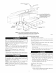
18-1N. MINIMUM
TO BURNERS
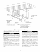
Fig. 16--Installation in a Garage
A93044
r!l I'JI-I_UII_" [q
When furnace is installed in a residential garage, it nmst be
installed so that bumers and ignition sources are located a
minimum of 18 in. above floor. The fumace nmst be located
or protected to avoid physical damage by vehicles. When
furnace is installed in a public garage, airplane hangar, or
other building having a hazardous atmosphere, the fumace
must be installed in accordance with NFGC or NSCNGPIC.
(See Fig. 16.)
INSTALLATION
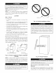
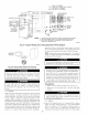
Step l--Leveling Legs (If Desired)
When furnace is used in upflow position with side inlet(s), leveling
legs may be desired. (See Fig. 17.) Install field-supplied,
corrosion-resistant 5/16-in. machine bolts and nuts.
i. Position furnace on its back. Locate and drill a 5/16 in.
diameter hole in each bottom comer of furnace. (See Fig. 17.)
Holes in bottom closure panel may be used as guide locations.
2. For each hole, install nut on bolt and then install bolt and nut
in hole. (Install flat washer if desired.)
3. Install another nut on other side of fumace base. (Install flat
washer if desired.)
4. Adjust outside nut to provide desired height, and tighten inside
nut to secure arrangement.
NOTE: Bottom closure must be used when leveling legs are used.
See Bottom Closure Panel section.
Step 2--Installation in Upflow and Downflow
Applications
NOTE: For downfiow applications, this furnace is approved for
use on combustible flooring when special base (available from
manufacturer) Part No. KGASB0201ALL is used. Special base is
not required when this fumace is installed on manufacturer's Coil
Assembly Part No. CD5 or CK5, or Coil Box Part No. KCAKC is
used.
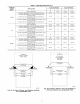
i. Determine application being installed from Table 1.
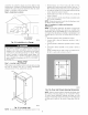
2. Construct hole in floor per dimensions specified in Table 1
and Fig. 18.
3. Construct plenum to dimensions specified in Table 1 and Fig.
18.
4. If downflow subbase (KGASB) is used, install as shown in
Fig. 19.
If Coil Assembly Part No. CD5 or CK5 or Coil Box Part No.
KCAKC is used, install as shown in Fig. 20.
A89014
Fig. 17--Leveling Legs
NOTE: The maximum length of bolt should not exceed i-i/2 in.
A96283
Fig. 18--Floor and Plenum Opening Dimensions
NOTE: Remove furnace perforated, discharge duct flanges when
they interfere with mating flanges on coil on downflow subbase.
To remove fumace perforated, discharge duct flange, use wide
duct pliers or duct flange tool or hand seamers to bend flange back
and forth until it breaks of£ Be careful of sharp edges. (See Fig.
21.)
14