
Operating instructions


P":_I[_o_
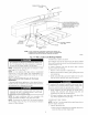
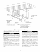
The condensate trap MUST be installed below furnace. See
Fig. 5 for dimensions. The drain connection to condensate
trap must also be properly sloped to an open &ain.
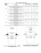
NOTE: Combustion-air and vent pipes are restricted to a mira-
mum length of 5 It. (See Table 7.)
NOTE: A 12-in. minimum offset pipe section is recommended
with short (5 to 8 It) vent systems. This recommendation is to
reduce excessive condensate &oplets from exiting the vent pipe.
(See Fig. i1 or 34.)
LOCATION
Step l--General
This furnace must
• be installed so the electrical components are protected from
water.
• not be installed directly on any combustible material other than
wood flooring (refer to SAFETY CONSIDERATIONS).
• be located so combustion-air and vent pipe nlaxinmm lengths
are not exceeded. Refer to Table 7.
• be located where available electric power and gas supplies meet
specifications on the furnace rating plate.
• be attached to an air distribution system and be located as close
to the center of the distribution system as possible. Refer to Air
Ducts section.
• be provided with ample space for servicing and cleaning.
Ahvays comply with minimum fire protection clearances
shown on the furnace clearance-to-combustibles label.
This furnace may be located in a confined space without special
provisions for dilution or ventilation air.
When a furnace is installed so that supply ducts carry air circulated
by the furnace to areas outside the space containing the furnace,
the return air shall also be handled by ducts sealed to furnace
casing. The ducts terminate outside the space containing the
furnace to ensure there will not be a negative pressure condition
within equipment room or space.
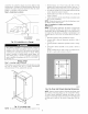
¥.,I [..T_luhd[0],'l
LEVEL (0") t
4
1/2" MAX TO
1/2" MAX
UPFLOW OR DOWNFLOW HORIZONTAL
A02146
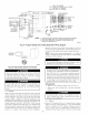
Fig. 13--Furnace Location for Proper Condensate
Drainage
NOTE: For upflowidownflow applications install furnace so that
it is level or pitched forward within 1/2-in. for proper furnace
operation. For horizontal applications pitch 1/4-in. minimum to
1/2-in. maximum forward to ensure proper condensate drainage
fi'om secondary heat exchangers. (See Fig. 13.)
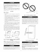
BACK
h
A93043
Fig. 14--Prohibit Installation on Back
Do not operate this furnace during construction. If the furnace
is required for temporary heating of buildings or structures
under construction, use clean outside air fi'ee of chlorine and
fluorine compounds for combustion and ventilation. These
compounds fore1 acids that corrode the heat exchangers.
These compounds are found in paneling and dry wall adhe-
sives, paints, thinners, masonry cleaning materials, and many
other solvents.
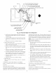
Fig. 15--Freeze Protection
A93058
¥.'_["_'] "/I
If furnace is installed in an unconditioned space where the
ambient temperatures may be 32°F or lower, freeze protection
measures nmsit be taken. (See Fig. 15.)
kv''1_]211X' -]
Do not install furnace on its back. Safety control operation
will be adversely affected. Never connect return-air ducts to
back of furnace. Failure to follow this warning could result in
fire, personal injury, or death. (See Fig. 14.)
Step 2--Furnace Location Relative to Cooling
Equipment
The cooling coil must be installed parallel with or on downstream
side of fumace to avoid condensation in heat exchanger. When
installed parallel with a furnace, dampers or other means used to
13