
User manual

14 Axxius 800 - Release 2.2
Quick Start
Chassis Connections
Chassis Connections
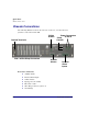
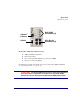
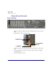
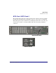
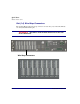
The following illustrations show all connectors on the rear, as well as the front
(interface card) of the Axxius 800.
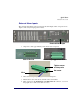
Back of the Axxius 800:
l Audible Alarms
l External Alarm Inputs
l Visible Alarms
l Input (power, P1 and P2)
l Bits Clock 1 and 2
l Wire Wrap Connectors (slots 1-8)
l Ground Lugs
Ground Terminals
Audible
Power Connectors
Visible
Clock
A and B
External
Alarm
Slot 1-8 Wire Wrap Connectors
A and BAlarms
Alarms
Inputs