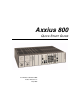
Axxius 800 QUICK START GUIDE Part Number: 002-0151-0006 Product Release: 2.
Copyright 2004 Carrier Access Corporation. All rights reserved. The information presented in this manual is subject to change without notice and does not represent a commitment on the part of Carrier Access Corporation. The hardware and software described herein are furnished under a license or non-disclosure agreement. The hardware, software, and manual may be used or copied only in accordance with the terms of this agreement.
PREFACE Preface Safety Information CAUTION! ALWAYS USE CAUTION WHEN INSTALLING TELEPHONE LINES. READ THE CAUTIONS BELOW FOR DETAILS ON SAFETY GUIDELINES TO PREVENT INJURY. l Never touch uninsulated telephone wires and terminals unless the telephone line has been disconnected at the Network Interface (NI) as voltage potentials as high as 300 VAC may be present across the transmit and receive pairs. l Only use No. 26 AWG or larger telecommunication line cord, to reduce the risk of fire.
Preface Electrostatic Discharge (ESD) Precautions Electrostatic Discharge (ESD) Precautions ESD can damage processors, circuit cards, and other electronic components. Always observe the following precautions before installing a system component. 1. Do not remove a component from its protective packaging until ready to install it. 2. Wear a wrist grounding strap and attach it to a metal part of the system unit before handling components.
QUICK START GUIDE In this Guide n Unpacking and Inspection n Installation Environment n Assembly of Axxius 800 n Rack Mounting n Compliant Installation n Chassis Connections n Connector Pinouts n LEDs n Provision a Unit
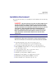
Quick Start Unpacking and Inspection Unpacking and Inspection WARNING! OBSERVE PRECAUTIONS FOR HANDLING ELECTROSTATIC DEVICES. 1. Inspect containers for damage during shipment. Report any damage to the freight carrier for possible insurance claims. 2. Compare packing list with office records. Report any discrepancies to the office. 3. Open shipping containers, be careful not to damage contents. 4. Inspect contents and report any damage. 5.
Quick Start Installation Environment Installation Environment The environment in which you are installing the Axxius 800 must meet the following conditions: DANGER! RESTRICTED ACCESS LOCATION FOR ACCESS 800: ACCESS CAN ONLY BE GAINED BY SERVICE PERSONNEL OR USERS WHO HAVE BEEN INSTRUCTED ABOUT THE POTENTIAL SAFETY HAZARDS THAT EXIST. ACCESS CAN ONLY BE GAINED TO THE EQUIPMENT LOCATION BY THE USE OF A TOOL OR LOCK AND KEY. TAKE PRECAUTIONS WHEN INSTALLING/SERVICING THE EQUIPMENT.
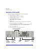
Quick Start Assembly of Axxius 800 Assembly of Axxius 800 The cards should be positioned according to the following guidelines: l Power Supply(s) 24 or 48 VDC Single Power Supply - slot Power 1 or Power 2 Dual Power Supplies - slot Power 1 and Power 2 l Controller card(s) DS1 or DS3 Single Controller card - slot A1 or A2 Dual Controller cards - slot A1 and A2 l Interface card The Interface card is designed with two boards that follow a single guide. l Service Cards can be in any slot 1 through 8.
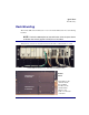
Quick Start Rack Mounting Rack Mounting The Axxius 800 can be mounted on a 19 or 23 inch rack with Carrier Access mounting brackets. NOTE: The Axxius 800 requires at least 3/4 inches of free air space above and below the chassis (approx 1/2 RU) for air circulation. Always leave at least 14" clearance in front of the unit, to add and remove cards. Axxius 800 mounted to a 19" rack with mounting brackets Bracket Ears to the front Bracket Ears to the back Axxius 800 - Release 2.
Quick Start Rack Mounting To maintain proper convection cooling, maintain at least 1/2 RU between the Axxius and any other equipment (each Axxius occupies 3 RU of rack space). Therefore, if one Axxius is mounted above another Axxius, then there would be a total of 1 RU between them (1/2 RU above the lower unit and 1/2 RU below the upper unit).
Quick Start Compliant Installation Compliant Installation WARNING! USE MINIMUM ALL TELECOMMUNICATION NETWORK CONNECTIONS MUST 26 AWG WIRE. 1. Mount unit in an area that meets Environment conditions, see “Installation Environment” on page 3. 2. Unit should have power supply(s), controller(s) and Interface cards installed before power up. NOTE: All cards (power supplies, controllers, interface, relay and service) slide into the unit in the same manner.
Quick Start Chassis Connections Chassis Connections The following illustrations show all connectors on the rear, as well as the front (interface card) of the Axxius 800.
Quick Start Chassis Connections 10Base-T Ethernet RS-232 DS3 (SMB) Connectors (4) DS1 (RJ-48) Connectors (4) Front of the Axxius 800 - Interface Card l l l l 10Base-T Ethernet (RJ-48C) RS-232 Craft Port DS3-1 and 2 Transmit and Receive connectors (SMB) DS1 (1-4) connectors (RJ-48) For information on this card and all connectors see the Axxius 800 User Manual “Control Panel Interfaces” on page 11.
Quick Start Chassis Connections Chassis Ground Connector Ground Terminals 1. Route wire (#6 or #8 AWG copper) from building ground to lug on Axxius 800. 2. Strip insulation off wire end, if necessary. Ground Lug Compression Screw Lug Barrel 3. Loosen compression screw until opening is large enough to accept ground wire. 4. Insert ground wire into lug barrel, beneath compression plate and tighten compression screw. 5. Attach ground lug to chassis 16 Axxius 800 - Release 2.
Quick Start Chassis Connections Power Connections There are three power supplies available with the Axxius 800; 24 VDC and 48 VDC and 48 VDC NI, all use this connector. The Axxius 800 supports a redundant power system, therefore there is INPUT (power) P1 and P2. Input Power Power Supply Rated Amperage Recommended External Input Fuse 24 VDC 5 Amp 7 Amp 48 VDC/48 VDC NI 2.5 Amp 3.
Quick Start Chassis Connections 5. Ensure that no bare wire shows after the wires are installed. Provided Connector (male) Tighten screws to clamp wires Set Screw + - 6. Plug connector in the INPUT (power) connector, as seen in the graphic and secure with set screws. 7. Apply power to connector. 8. Verify with voltmeter that voltage is correct and polarity is correct. 9. Plug connector(s) into the Axxius 800. 10. A green light should appear on the DC Input LED on the front of the Power Supply.
Quick Start Chassis Connections External Alarm Inputs The external alarm input connector supports 10 alarm inputs and is composed of two 10-pin connectors (two input pairs for each). External Alarm Input 1. Strip wire so that approximately 5/16 of bare wire is exposed. back of Axxius Connector plugged into Axxius Tighten screw to clamp wire Set screw Wire 2. Insert wire into opening and tighten screw to clamp wire. 3. Ensure that no bare wire shows after the wires are installed. 4.
Quick Start Chassis Connections Visible and Audible Alarms The external alarm connectors are six-pin connectors with two output pairs for each alarm level (pins 1 & 2 for minor, pins 3 & 4 for major and 5 & 6 for critical alarms). Visible Alarm Audible Alarm 1. Strip wire so that approximately 5/16 of bare wire is exposed. pin 1 back of Axxius Wire Connectors plugged into Axxius Set screw Tighten screw to clamp wire 2. Insert wire into opening and tighten screw to clamp wire. 3.
Quick Start Chassis Connections BITS Clock 1/BITS Clock 2 The external alarm connectors are three-pin wire-wrap connectors. One for each, Tip (T), Ring (R) and Shield (S). Tip and Ring are the two connections for the 100 ohm differential signal to the box. Shield is for grounding the shield of the clock cable to the Axxius. If the customer is not using shielded cable, then only the Tip and Ring is connected. Bits Clock 1 and 2 back of Axxius Axxius 800 - Release 2.
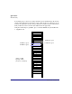
Quick Start Chassis Connections Slot (1-8) Wire Wrap Connectors The Axxius 800 provides wire wrap connectors for each slot (1-8) of the unit. Pinouts are clearly labeled with the pins. WARNING! DISCONNECT FROM NETWORK BEFORE INSTALLING WIRE WRAP CONNECTIONS. Wire Wrap Connectors 22 Axxius 800 - Release 2.
Quick Start Chassis Connections Wire Wrap Pinout for 4 Wire Services Wire Wrap Pins T1 Name Description 1RX Port 1 Receive Ring Receive from DS1 network Receive Tip Receive from DS1 network Transmit Ring To DS1 network Transmit Tip To DS1 network Receive Ring Receive from DS1 network Receive Tip Receive from DS1 network Transmit Ring To DS1 network Transmit Tip To DS1 network Receive Ring Receive from DS1 network Receive Tip Receive from DS1 network Transmit Ring To DS1 network
Quick Start Chassis Connections Wire Wrap Pinout 2 Wire Services Wire Wrap Pins 24 Description T1 Channel 1 Transmit Tip R1 Channel 1 Transmit Ring T2 Channel 2 Transmit Tip R2 Channel 2 Transmit Ring T3 Channel 3 Transmit Tip R3 Channel 3 Transmit Ring T4 Channel 4 Transmit Tip R4 Channel 4 Transmit Ring T5 Channel 5 Transmit Tip R5 Channel 5 Transmit Ring T6 Channel 6 Transmit Tip R6 Channel 6 Transmit Ring T7 Channel 7 Transmit Tip R7 Channel 7 Transmit Ring T8 Channel 8
Quick Start Chassis Connections Standard Telco Color Code Circuit connections are made at the wire wrap connectors.
Quick Start Chassis Connections Pair 26 Pin Location Function Color Code 15 40 15 Tip Channel 15 Ring Channel 15 Black/Slate Slate/Black 16 41 16 Tip Channel 16 Ring Channel 16 Yellow/Blue Blue/Yellow 17 42 17 Tip Channel 17 Ring Channel 17 Yellow/Orange Orange/Yellow 18 43 18 Tip Channel 18 Ring Channel 18 Yellow/Green Green/Yellow 19 44 19 Tip Channel 19 Ring Channel 19 Yellow/Brown Brown/Yellow 20 45 20 Tip Channel 20 Ring Channel 20 Yellow/Slate Slate/Yellow 21 46 21 Tip
Quick Start Connector Pinouts Connector Pinouts l Control Panel Interface Card l OCU-DP (DDS RJ-48S) l Quad T1/ADPCM Cards RJ-48 Connector l TSR Card 10/100Base-TX Ethernet l V.35 DCE (DB-26) Control Panel Interface Card RS-232 Craft Port (Female DB-9) 1 The RS-232 craft port connects via a female DB-9 connector on the Axxius 800.
Quick Start Connector Pinouts DS1 Connection Ports 1 8 1 8 The DS1 connection ports are each equipped with a standard RJ-48C (female) on the Axxius 800 unit.
Quick Start Connector Pinouts OCU-DP (DDS RJ-48S) The pinout for RJ-48S female is as follows: 1 Pin Function Description 1 Receives Data (R-1) From Customer to Network Interface 2 Receives Data (T-1) From Customer to Network Interface 3-6 Not Used 7 Transmits Data (T) From Network Interface to Customer 8 Transmits Data (R) From Network Interface to Customer 8 Note: The above listed functions are relative to this port. Axxius 800 - Release 2.
Quick Start Connector Pinouts Quad T1/ADPCM Cards RJ-48 Connector There are four RJ-48 (female) connectors on the front of the Quad T1 and Quad DS1 ADPCM Card.
Quick Start Connector Pinouts V.35 DCE (DB-26) The V.35 DCE data port connection is made at the sub-miniature DB-26 connector on the Axxius 800 using the 10-foot, 25-foot, or 50 foot Carrier Access DTE V.35 cable equipped with a sub-miniature DB-26 connector and a 34-pin Winchester connector. This cable is used to connect the Axxius 800 V.35 DCE data ports to synchronous V.35 DTE data sources up to 1.536 Mbps, all rates (1-24) Nx56 or Nx64 channel-rate progression. The Carrier Access Corporation V.
Quick Start LEDs LEDs This section provides details about the LEDs on the Axxius 800. 32 l Control Panel LEDs l DS1 Controller Card l DS3 Controller Card l 24VDC and 48VDC Power Supplies l FXO Card l ISDN BRI Cards l OCU-DP Card l POTS Cards l Quad T1/DS1 ADPCM Cards l Quad TSR Card l V.35 Card l Low Speed Protection Card Axxius 800 - Release 2.
Quick Start LEDs Control Panel LEDs Alarm LEDs LED State Description CRITICAL Off No critical alarms present Red Critical alarms present Off No major alarms present Red Major alarm present Off No minor alarms present Red Minor alarms present Off Normal mode. No alarms are being suppressed. Red Alarm cutoff active. One or more active alarms suppressed. MAJOR MINOR ACO Axxius 800 - Release 2.
Quick Start LEDs Ethernet LEDs LED State Description STATUS Off Link Down Green Link Up Flashing Green Traffic on Link When Status LED is on or flashing: 34 LED State Description 10/100 Off Link is 10 Mb Green Link is 100 Mb Axxius 800 - Release 2.
Quick Start LEDs DS1 Controller Card The DS1 Controller has a set of six LEDs. The table below describes each LED.
Quick Start LEDs DS3 Controller Card The DS3 Controller has a set of six LEDs. The table below describes each LED.
Quick Start LEDs 24VDC and 48VDC Power Supplies Both power supply cards have identical LEDs, as described in the table below. LED State Description DC Input Off DC input missing or fuse blown Yellow Under or over-voltage Green Valid DC input present Off No 5V output (neither power supply operating) Red 5V output not functioning (2nd unit operating) Green 5V output good Output Voltage Status Axxius 800 - Release 2.
Quick Start LEDs FXO Card Each FXO port on a card has its own LED, described in the table below.
Quick Start LEDs OCU-DP Card There are two LEDs for each channel on the OCU-DP card. The function for each LED is listed below: State LED Description Yellow Flickering ALL Boot Software in control. Green (walking down) Red (walking up) ALL Application Software in control (repeated 3.5 times). Red, slow flash ALL In Boot. Application flash code checksums did not match and Boot is waiting for application download.
Quick Start LEDs Single Channel POTS Cards The POTs channel LED (left) status is described in the table below. State Loop Start Meaning Off Calling Party Disconnect Green Idle Red N/A Yellow Call in progress Flashing green Ringing The second LED (right) is a status LED for the MODEM. 40 State Loop Start Meaning Off Calling Party Disconnect Green Ringing Yellow Carrier Detect Axxius 800 - Release 2.
Quick Start LEDs Quad DS1/E1, Quad T1, and Quad DS1 ADPCM Cards Each channel on the Quad DS1/E1, Quad T1 and Quad DS1 ADPCM cards have two LEDs per port. The description of the top LED is shown below, the bottom LED is not used with this application. Top LED (active) Bottom LED (not used) Axxius 800 - Release 2.
Quick Start LEDs Quad TSR Card The Quad TSR has 2 LEDs per port.
Quick Start LEDs V.35 Card Each V.35 port has its own LED, as shown in the table below. State Description Off No T1 Assignment Green Normal (CD/RTS) Active Red CD inactive (T1-side failure) Yellow RTS inactive (equipment-side failure) Flashing Yellow Loopback toward T1 or equipment loop test Flashing Green Loopback toward equipment or network loop test Axxius 800 - Release 2.
Quick Start LEDs Low Speed Protection Card The Low Speed Protection card has 10 LEDs, which are defined below. LED State Description STAT Green Enabled Red Disabled Flashing Green Disabled Off The corresponding slot is not being protected via the Protection card. Yellow One or more ports of the corresponding slot are being protected via the Protection card. Slot Status (1-8) Each channel on the Quad T1 card has two LEDs.
Quick Start Provision a Unit Provision a Unit l Local using CLI, Telnet, Modem or SNMP (Valet) l Remotely over an in-band DS0 l Remotely over an SNMP network using NetworkValet EMS Command Line Interface (CLI) You can access the CLI using either of the following methods: l RS-232 connected to the DB-9 port.
Quick Start Provision a Unit Basic System Setup Initial Setup Use the following commands for your initial setup, for further information see the specific command listed in Chapter 5, CLI Commands. 46 Command Description set date dd/mm/yyyy Set the system date, using the format day/month/year. See the set date command for details. set time {hh:mm:ss} Set the system time. See the set time command for details. set id {“id-name”} Set the systemID name. Remember to enclose this name in quotes.
Quick Start Provision a Unit Set Up Security Use the following commands to set up the security on the Axxius 800. Command Description set user {"user-name"} level {1-3} Specify the user name and the security level. See set user command for details. set user {"user-name"} password Set a password for the user. See set user command for details. Set Up a DS0/Channel Use the following commands to set up a DS0. Command Description set {ds0-addr} type {data|voice} Set the channel type.
Quick Start Provision a Unit Set Up a DS1/T1 Use the following commands to set up a DS1. See the set (ds1) command for more details. 48 Command Description set {ds1-addr} up Activate the port. set {ds1-addr} fdl {none|t1403} Set the Facilities Data Link (FDL) capabilities. set {ds1-addr} framing {d4| esf} Set the framing option for the DS1. set {ds1-addr} id {"id-name"} Set the circuit identification name for the DS1. set {ds1-addr} lbo {1-8} Set the line buildout value for the DS1.
Quick Start Provision a Unit Set Up a DS3 Use the following commands for DS3 setup. See the set (ds3) command for more details. Command Description set {ds3-addr} up Activate the port. set {ds3-addr} id {"id-name"} Set the DS3 ID. set {ds3-addr} clock {loop|normal} Set the transmit clock source. set {ds3-addr} berthreshold {value} Set the Bit Error Rate protection switchover threshold. set {ds3-addr} dejitter {off|on} Set the De-jitter buffer on or off.
Quick Start Provision a Unit Setup DS1 ADPCM Before configuring the DS1 ADPCM card, there are some basics that need to be considered: l All DS0s to be compressed reside on T1 number 1 of the ADPCM card l ADPCM is capable of transporting any combination of 64 and 32K l All 24 DS0s can be transported either compressed or uncompressed, but not both at the same time. l All DS0s to be compressed must be set to type data.
Quick Start Provision a Unit Establish a Static Channel Connection Use the following commands to establish a static channel connection. Command Description set {ds0-addr} type {voice|data} Set the channel type for the channel you want to map. See set (ds0) command for details. set {ds0-addr} signal {emdw| emi|emicpd|emw|gs|ls} Set the signaling option for the channel you want to map. See set (ds0) command for details. connect {slot:port} {slot:port} Connect the channels.
Quick Start Provision a Unit Set Up a Single Channel POTS card Use the following commands to set up a POTS card. Command Description set {fxsPS-addr|fxsPSM-addr} {ls|lsrb} Set the signaling option for the port. See the set (fxsPS or fxsPSM) command for details. set {fxsPS-addr|fxsPSM-addr} rxgain {n} Set the receive gain/loss in dB. See the set (fxsPS or fxsPSM) command for details. set {fxsPS-addr|fxsPSM-addr} txgain {n} Set the transmit gain/loss in dB.
Quick Start Provision a Unit Upgrade the Axxius 800 Software Use the following commands to determine the Controller software level, then upgrade the software to the latest version. Command Description status equipment Determine the software level. See the status equipment command for more information. load tftp {ip-addr} {"filename"} (or load xmodem) Load the new software to the Axxius 800. See the load tftp and load xmodem command for more information. Axxius 800 - Release 2.
Quick Start Provision a Unit Basic Setup of a Protected System To set up a Protected System, the following is required: l l l Axxius 800 with software 1.2 or higher Low Speed Protection (Relay) card 2 - 6 Quad T1 Cards (1 designated as Backup card, others to be protected) Use the following steps to set up a Protected System. 1. Install a Relay card in the Axxius Relay slot. 2. Set the jumpers on the Quad T1 cards to route the signal to the wire wrap pins. 3.