Axxius 800 USER MANUAL Part Number: 770-0104 AG Product Release: 2.
Copyright 2004 Carrier Access Corporation. All rights reserved. The information presented in this manual is subject to change without notice and does not represent a commitment on the part of Carrier Access Corporation. The hardware and software described herein are furnished under a license or non-disclosure agreement. The hardware, software, and manual may be used or copied only in accordance with the terms of this agreement.
PREFACE Preface Compliance Safety The Axxius 800 is certified by Underwriters Laboratories and is in compliance with UL60950, 3rd Edition; Safety of Information Technology Equipment and CSA/C22.2 No 60950. FCC Requirements, Part 15 This equipment has been tested and found to comply with the limits for a Class A digital device pursuant to Part 15 of the Federal Communications Rules.
Preface Compliance The Facility Interface Code (FIC) associated with each private line application represents the type of service that will be provided by the telephone company. The following are currently registered: Port: FIC: SOC: Jack: HD Quad T1 1.544 Mbps 04DU9-BN 6.0F RJ48C HD Quad T1 1.544 Mbps 04DU9-DN 6.0F RJ48C HD Quad T1 1.544 Mbps 04DU9-1KN 6.0F RJ48C HD Quad T1 1.544 Mbps 04DU9-1SN 6.0F RJ48C HD Quad DS1 ADPCM 1.544 Mbps 04DU9-BN 6.0F RJ48C HD Quad DS1 ADPCM 1.
Preface Compliance Industry Canada CS-03 Registration Number: IC: 2638A-800 ’’NOTICE: This equipment meets the applicable Industry Canada Terminal Equipment Technical Specifications. This is confirmed by the registration number. The abbreviation, IC, before the registration number signifies that registration was performed based on a Declaration of Conformity indicating that Industry Canada technical specifications were met. It does not imply that Industry Canada approved the equipment.
Preface Safety Information Safety Information CAUTION! ALWAYS USE CAUTION WHEN INSTALLING TELEPHONE LINES. READ THE CAUTIONS BELOW FOR DETAILS ON SAFETY GUIDELINES TO PREVENT INJURY. l Never touch uninsulated telephone wires and terminals unless the telephone line has been disconnected at the Network Interface (NI) as voltage potentials as high as 300 VAC may be present across the transmit and receive pairs. l Only use No. 26 AWG or larger telecommunication line cord, to reduce the risk of fire.
Preface Notices Notices This manual contains important information and warnings that must be followed to ensure safe operation of the equipment. DANGER! A DANGER NOTICE INDICATES THE PRESENCE OF A HAZARD THAT CAN OR WILL CAUSE DEATH OR SEVERE PERSONAL INJURY IF THE HAZARD IS NOT AVOIDED. CAUTION! A CAUTION NOTICE INDICATES THE POSSIBILITY OF INTERRUPTING NETWORK SERVICE IF THE HAZARD IS NOT AVOIDED. WARNING! A WARNING NOTICE INDICATES THE POSSIBILITY OF EQUIPMENT DAMAGE IF THE HAZARD IS NOT AVOIDED.
Preface Electrostatic Discharge (ESD) Precautions Electrostatic Discharge (ESD) Precautions ESD can damage processors, circuit cards, and other electronic components. Always observe the following precautions before installing a system component. 1. Do not remove a component from its protective packaging until ready to install it. 2. Wear a wrist grounding strap and attach it to a metal part of the system unit before handling components.
Preface Warranty Warranty Carrier Access Corporation conditionally warrants to BUYER that PRODUCTS are free from substantial defect in material and workmanship under normal use given proper installation and maintenance for the period of five years from the date of shipment by Carrier Access Corporation. BUYER will promptly notify Carrier Access Corporation of any defect in the PRODUCT.
Preface Warranty Warranty Product Returns Before returning any equipment to Carrier Access Corporation, first contact the distributor or dealer from which you purchased the product. A Return Material Authorization (RMA) number is required for all equipment returned to Carrier Access Corporation. Call Carrier Access Corporation Customer Support at (800) 786-9929 or (303) 442-5455 for RMA number, repair/warranty information and shipping instructions.
TABLE OF CONTENTS Table of Contents Preface Compliance . . . . . . . . . . . . . . . . . . . . . . . . . . . . . . . . . . . . . . . . . . . . . . . . . iii Safety . . . . . . . . . . . . . . . . . . . . . . . . . . . . . . . . . . . . . . . . . . . . . . . . . iii FCC Requirements, Part 15 . . . . . . . . . . . . . . . . . . . . . . . . . . . . . . . . iii FCC Requirements, Part 68 . . . . . . . . . . . . . . . . . . . . . . . . . . . . . . . . iii Industry Canada CS-03 . . . . . . . . . . . . . . . . . .
Table of Contents Low Speed Protection card . . . . . . . . . . . . . . . . . . . . . . . . . . . . . . . . . . 1-6 Power Supplies . . . . . . . . . . . . . . . . . . . . . . . . . . . . . . . . . . . . . . . . . . . . . . 1-6 24 VDC Power Supply. . . . . . . . . . . . . . . . . . . . . . . . . . . . . . . . . . . . . . 1-6 48 VDC I48 Power Supply . . . . . . . . . . . . . . . . . . . . . . . . . . . . . . . . . . 1-6 48 VDC NI48 Power Supply . . . . . . . . . . . . . . . . . . . . . . . . . . . . . . . .
Table of Contents 2 Physical Installation Unpacking and Inspection. . . . . . . . . . . . . . . . . . . . . . . . . . . . . . . . . . . . . Installation Environment . . . . . . . . . . . . . . . . . . . . . . . . . . . . . . . . . . . . . . Assembly of Axxius 800 . . . . . . . . . . . . . . . . . . . . . . . . . . . . . . . . . . . . . . Rack Mounting . . . . . . . . . . . . . . . . . . . . . . . . . . . . . . . . . . . . . . . . . . . . .
Table of Contents Quick Configuration Reload. . . . . . . . . . . . . . . . . . . . . . . . . . . . . . . . . . . 4-11 Setup of DS0 Management Channel . . . . . . . . . . . . . . . . . . . . . . . . . . . . 4-14 Equipment Required. . . . . . . . . . . . . . . . . . . . . . . . . . . . . . . . . . . . . . . 4-15 Set IP Configuration of PC . . . . . . . . . . . . . . . . . . . . . . . . . . . . . . . . . 4-17 Configuring the Axxius Router . . . . . . . . . . . . . . . . . . . . . . . . . . . . . .
Table of Contents clear key . . . . . . . . . . . . . . . . . . . . . . . . . . . . . . . . . . . . . . . . . . . . . . . clear log. . . . . . . . . . . . . . . . . . . . . . . . . . . . . . . . . . . . . . . . . . . . . . . . clear (ocudp) performance . . . . . . . . . . . . . . . . . . . . . . . . . . . . . . . . . clear (router) ip address table . . . . . . . . . . . . . . . . . . . . . . . . . . . . . . . clear (router) mac address table . . . . . . . . . . . . . . . . . . . . . . . . . . . . .
Table of Contents log . . . . . . . . . . . . . . . . . . . . . . . . . . . . . . . . . . . . . . . . . . . . . . . . . . . . . . 5-62 ping . . . . . . . . . . . . . . . . . . . . . . . . . . . . . . . . . . . . . . . . . . . . . . . . . . . . . 5-63 print . . . . . . . . . . . . . . . . . . . . . . . . . . . . . . . . . . . . . . . . . . . . . . . . . . . . . 5-64 print config . . . . . . . . . . . . . . . . . . . . . . . . . . . . . . . . . . . . . . . . . . . . . . 5-64 print help . . . . . . . . . . .
Table of Contents set ipds0 . . . . . . . . . . . . . . . . . . . . . . . . . . . . . . . . . . . . . . . . . . . . . . . 5-90 set key . . . . . . . . . . . . . . . . . . . . . . . . . . . . . . . . . . . . . . . . . . . . . . . . . 5-91 set login auth . . . . . . . . . . . . . . . . . . . . . . . . . . . . . . . . . . . . . . . . . . . . 5-91 set login support . . . . . . . . . . . . . . . . . . . . . . . . . . . . . . . . . . . . . . . . . 5-92 set lsbackup. . . . . . . . . . . . . . . . . . . . . . . .
Table of Contents set (router) rip. . . . . . . . . . . . . . . . . . . . . . . . . . . . . . . . . . . . . . . . . . . 5-131 set (router) snmp . . . . . . . . . . . . . . . . . . . . . . . . . . . . . . . . . . . . . . . . 5-132 set (router) stp . . . . . . . . . . . . . . . . . . . . . . . . . . . . . . . . . . . . . . . . . . 5-134 set (router) syslog. . . . . . . . . . . . . . . . . . . . . . . . . . . . . . . . . . . . . . . . 5-137 set (router-lan) filter forward . . . . . . . . . . . . . . . . . . .
Table of Contents set (v35) . . . . . . . . . . . . . . . . . . . . . . . . . . . . . . . . . . . . . . . . . . . . . . set (v54) . . . . . . . . . . . . . . . . . . . . . . . . . . . . . . . . . . . . . . . . . . . . . . set verification. . . . . . . . . . . . . . . . . . . . . . . . . . . . . . . . . . . . . . . . . . show . . . . . . . . . . . . . . . . . . . . . . . . . . . . . . . . . . . . . . . . . . . . . . . . . . . show (adpcm) . . . . . . . . . . . . . . . . . . . . . . . . . . . . . . . . . . .
Table of Contents show (router) lmi . . . . . . . . . . . . . . . . . . . . . . . . . . . . . . . . . . . . . . . . 5-197 show (router) login . . . . . . . . . . . . . . . . . . . . . . . . . . . . . . . . . . . . . . . 5-197 show (router) ntp . . . . . . . . . . . . . . . . . . . . . . . . . . . . . . . . . . . . . . . . 5-198 show (router) port. . . . . . . . . . . . . . . . . . . . . . . . . . . . . . . . . . . . . . . . 5-199 show (router) ppp . . . . . . . . . . . . . . . . . . . . . . . . . . . . . .
Table of Contents status (adpcm) . . . . . . . . . . . . . . . . . . . . . . . . . . . . . . . . . . . . . . . . . . status (adpcm) performance . . . . . . . . . . . . . . . . . . . . . . . . . . . . . . . status (adpcm) performance history . . . . . . . . . . . . . . . . . . . . . . . . . status (bri) . . . . . . . . . . . . . . . . . . . . . . . . . . . . . . . . . . . . . . . . . . . . . status (bri) performance . . . . . . . . . . . . . . . . . . . . . . . . . . . . . . . . . .
Table of Contents telnet (router) . . . . . . . . . . . . . . . . . . . . . . . . . . . . . . . . . . . . . . . . . . . 5-260 trace route . . . . . . . . . . . . . . . . . . . . . . . . . . . . . . . . . . . . . . . . . . . . . . . 5-261 tracert (router) . . . . . . . . . . . . . . . . . . . . . . . . . . . . . . . . . . . . . . . . . . 5-261 6 DS1 Controller Card Overview . . . . . . . . . . . . . . . . . . . . . . . . . . . . . . . . . . . . . . . . . . . . . . . . . . 6-2 Features. . . . . . . . . . .
Table of Contents Clocking . . . . . . . . . . . . . . . . . . . . . . . . . . . . . . . . . . . . . . . . . . . . . . . . 7-5 Alarms. . . . . . . . . . . . . . . . . . . . . . . . . . . . . . . . . . . . . . . . . . . . . . . . . . 7-5 Testing and Diagnostics . . . . . . . . . . . . . . . . . . . . . . . . . . . . . . . . . . . . 7-6 Power Consumption . . . . . . . . . . . . . . . . . . . . . . . . . . . . . . . . . . . . . . . 7-6 Environment . . . . . . . . . . . . . . . . . . . . . . . . . . . . . . .
Table of Contents 9 ISDN BRI Card Overview . . . . . . . . . . . . . . . . . . . . . . . . . . . . . . . . . . . . . . . . . . . . . . . . . . 9-2 ISDN BRI. . . . . . . . . . . . . . . . . . . . . . . . . . . . . . . . . . . . . . . . . . . . . . . . 9-2 3-DS0 BRITE Mode . . . . . . . . . . . . . . . . . . . . . . . . . . . . . . . . . . . . . . . 9-2 Features. . . . . . . . . . . . . . . . . . . . . . . . . . . . . . . . . . . . . . . . . . . . . . . . . . . . 9-3 Technical Specifications. . . . . . . .
Table of Contents Power Consumption . . . . . . . . . . . . . . . . . . . . . . . . . . . . . . . . . . . . . . 10-6 Environment . . . . . . . . . . . . . . . . . . . . . . . . . . . . . . . . . . . . . . . . . . . . 10-6 Physical . . . . . . . . . . . . . . . . . . . . . . . . . . . . . . . . . . . . . . . . . . . . . . . . 10-6 Card Configuration . . . . . . . . . . . . . . . . . . . . . . . . . . . . . . . . . . . . . . . . . 10-7 CLI Commands. . . . . . . . . . . . . . . . . . . . . . . . . . . . . . .
Table of Contents 12 Power Supply Overview . . . . . . . . . . . . . . . . . . . . . . . . . . . . . . . . . . . . . . . . . . . . . . . . . 12-2 Features. . . . . . . . . . . . . . . . . . . . . . . . . . . . . . . . . . . . . . . . . . . . . . . . . . . 12-2 Technical Specifications. . . . . . . . . . . . . . . . . . . . . . . . . . . . . . . . . . . . . . 12-3 Components . . . . . . . . . . . . . . . . . . . . . . . . . . . . . . . . . . . . . . . . . . . . . 12-3 Electrical Input Characteristics . . .
Table of Contents Card Configuration . . . . . . . . . . . . . . . . . . . . . . . . . . . . . . . . . . . . . . . . . 13-6 CLI Commands. . . . . . . . . . . . . . . . . . . . . . . . . . . . . . . . . . . . . . . . . . 13-6 Basic Setup . . . . . . . . . . . . . . . . . . . . . . . . . . . . . . . . . . . . . . . . . . . . . 13-8 Cross-Connects . . . . . . . . . . . . . . . . . . . . . . . . . . . . . . . . . . . . . . . . . . 13-9 Jumper Settings . . . . . . . . . . . . . . . . . . . . . . . . . . . . . .
Table of Contents 15 Terminal Server Router Card Overview . . . . . . . . . . . . . . . . . . . . . . . . . . . . . . . . . . . . . . . . . . . . . . . . . 15-2 Quad TSR with TBOS . . . . . . . . . . . . . . . . . . . . . . . . . . . . . . . . . . . . . 15-2 Features. . . . . . . . . . . . . . . . . . . . . . . . . . . . . . . . . . . . . . . . . . . . . . . . . . . 15-3 Additional Features on a TSR Card with TBOS . . . . . . . . . . . . . . . . . 15-3 Technical Specifications. . . . . . . . . . . . . . .
Table of Contents 16 V.35/.54 Card Overview . . . . . . . . . . . . . . . . . . . . . . . . . . . . . . . . . . . . . . . . . . . . . . . . . Features . . . . . . . . . . . . . . . . . . . . . . . . . . . . . . . . . . . . . . . . . . . . . . . . . . Additional V.54 Features . . . . . . . . . . . . . . . . . . . . . . . . . . . . . . . . . . Technical Specifications . . . . . . . . . . . . . . . . . . . . . . . . . . . . . . . . . . . . . Controller Software Required . . . . . . . . . . . . . . . . . . .
Table of Contents Power . . . . . . . . . . . . . . . . . . . . . . . . . . . . . . . . . . . . . . . . . . . . . . . . . . 17-5 Environment. . . . . . . . . . . . . . . . . . . . . . . . . . . . . . . . . . . . . . . . . . . . . 17-5 Physical . . . . . . . . . . . . . . . . . . . . . . . . . . . . . . . . . . . . . . . . . . . . . . . . 17-5 Card Configuration. . . . . . . . . . . . . . . . . . . . . . . . . . . . . . . . . . . . . . . . . . 17-6 CLI Commands . . . . . . . . . . . . . . . . . . . . . . .
Table of Contents C Loopback Tests Alarms . . . . . . . . . . . . . . . . . . . . . . . . . . . . . . . . . . . . . . . . . . . . . . . . . . . . C-2 Test Alarm . . . . . . . . . . . . . . . . . . . . . . . . . . . . . . . . . . . . . . . . . . . . . . C-2 Identify Alarm. . . . . . . . . . . . . . . . . . . . . . . . . . . . . . . . . . . . . . . . . . . . C-2 Logs. . . . . . . . . . . . . . . . . . . . . . . . . . . . . . . . . . . . . . . . . . . . . . . . . . . . . . C-5 Status and Performance. . . . .
Table of Contents xxxii Axxius 800 - Release 2.
CHAPTER Base Platform In this Chapter n Overview n Features n Technical Specifications n Chassis n Built-In Card Handles n Management Ports n Local and Remote Management n Control Panel Interfaces n Control Panel LEDs n ACO
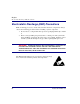
Base Platform Overview Overview The Axxius 800 Access Integration Platform solves today’s problems of multiple boxes, scalability, space, power, and environmental constraints associated with delivering voice and data services. The Axxius 800 defines a new level of functionality and performance for the access needs of both wireless and wireline service providers, and enables them to groom and deliver services for more revenue at dramatically lower costs.
Base Platform Features The Control Panel Interface card provides front access to all the physical interfaces of the DS1 or DS3 Controller cards. It provides four RJ-48C DS1 connections when using the DS1 Controller and two sets of DS3 SMB interfaces when using the DS3 Controller. Additionally, the Control Panel Interface Card provides the RS-232 and 10/100Base-TX Ethernet management connections for system configuration and control.
Base Platform Controllers Controllers The Axxius 800 has two controllers available, one controller can support the system, however with two controller (same type) the system is redundant. Dual DS3 Controller Features two DS3 ports with integrated 3/1/0 cross-connect matrix, providing nonblocking connectivity between the DS3 Controller and any of the 8 service card slots.
Base Platform Service Cards OCU-DP Service card The OCU-DP service card is available in a Single or Quad port option. The OCU-DP interface service allows Digital Data Service (DDS) circuit terminations on the Adit 600 platform. Provides the electrical and physical termination of a 4-wire DDS baseband connection which interfaces with a remote CSU/DSU.
Base Platform Power Supplies Low Speed Protection card Low speed protection provides backup circuitry for any T1 service port on any Quad T1 service card in the Axxius chassis. The Relay card provides the physical connectivity between the “Protected” T1 service port and the “Backup” T1 service port. Connectivity exists between the Quad T1 service card and the Relay card via the backplane pins only. Power Supplies 24 VDC Power Supply Provides the a standard +24 VDC power supply.
Base Platform Technical Specifications Capacities l 2 x Power Supply cards l 2 x DS3 or DS1 Controller cards l 1 x Control Panel Interface card l 8 x universal service cards l 36 T1 ports (8 x Quad T1 service cards + 4 on DS1 Controller) l 1536 DS0 non-blocking cross-connect capability Redundancy l 1:1 Controllers (automatic switchover) for provisioning redundancy l 1:7 T1 interface protection ratio with Low-Speed Interface Protection card l 1 + 1 Power Supplies Control Panel Interfaces l 4 x RJ-48C jack
Base Platform Technical Specifications Alarm Connectors The alarm contact outputs are per Telcordia definitions for visible and audible. They operate per the spec with the exception that the audible outputs can be disabled with the ACO button. l The alarm output contacts are designed for use at 48V nominal with a current draw of 0.5A maximum. l The alarm inputs are dry contact with a current capacity of 10mA. Network Standards l ANSI/TIA - T1.
Base Platform Chassis Chassis Future Development Power Supplies (P1 & P2) Controller Cards (A1 & A2) Ground Terminals Interface Card Future Development Slot 1-8 Wire-Wrap Connectors Axxius 800 - Release 2.
Base Platform Built-In Card Handles Built-In Card Handles Several of the cards for the Axxius 800 are designed with a handle built into the faceplate to assist in the removal of the card from the chassis. This handle slides out away from the unit, creating a handle for a more effective grip. The Controller cards and the Single Channel POTS card have this feature.
Base Platform Control Panel Interfaces Control Panel Interfaces 10Base-T Ethernet RS-232 DS3 (SMB) Connectors (4) DS1 (RJ-48) Connectors (4) SMB connector (female) The recommended mate for the SMB connector is an SMB right angle crimp connector. Axxius 800 - Release 2.
Base Platform Control Panel Interfaces RS-232 Craft Port (Female DB-9) The RS-232 craft port connects via a female DB-9 connector on the Axxius 800. 1 5 6 9 The pinouts are as follows: Pin Number Direction Description 1 Outbound Carrier Detect 2 Outbound Receive Data 3 Inbound Transmit Data 4 Inbound Data Terminal Ready 5 6 Outbound Data Set Ready 7 Inbound Request to Send 8 Outbound Clear to Send 9 1-12 Signal Ground Not Connected Axxius 800 - Release 2.
Base Platform Control Panel Interfaces DS1 Connection Ports 1 8 1 8 The DS1 connection ports are each equipped with a standard RJ-28C (female) on the Axxius 800 unit.
Base Platform Control Panel Interfaces Control Panel Interface Card Jumpers The Control Panel Interface card is provided with a jumper that allows the user to put a -3 dB pad in the transmit DS3 signal path to lower the output to a shorter line length. This prevents errors when working with very short cables. There is a simple drawing to assist in setting the Control Panel Interface jumpers. The jumpers in the second graphic are set to the position farthest from the faceplate, they are set to -3dB.
Base Platform Control Panel LEDs Control Panel LEDs Alarm LEDs LED State Description CRITICAL Off No critical alarms present Red Critical alarms present Off No major alarms present Red Major alarm present Off No minor alarms present Red Minor alarms present Off Normal mode. No alarms are being suppressed. Red Alarm cutoff active. One or more active alarms suppressed. MAJOR MINOR ACO Axxius 800 - Release 2.
Base Platform Control Panel LEDs Ethernet LEDs LED State Description STATUS Off Link Down Green Link Up Flashing Green Traffic on Link When Status LED is on or flashing: 1-16 LED State Description 10/100 Off Link is 10 Mb Green Link is 100 Mb Axxius 800 - Release 2.
Base Platform ACO ACO The Alarm Cutoff feature permits the operator to temporarily silence the alarm outputs while testing and repairing the Axxius 800. ACO does not stop alarm messages. Pressing the ACO pushbutton switch disables the alarm relays and lights the ACO status LED. This keeps the relay contacts open on the Alarm Output connector. If another alarm occurs, the alarm relays will be enabled again and the ACO status LED will go off.
Base Platform ACO 1-18 Axxius 800 - Release 2.
CHAPTER Physical Installation In this Chapter n Unpacking and Inspection n Installation Environment n Assembly of Axxius 800 n Rack Mounting
Physical Installation Unpacking and Inspection Unpacking and Inspection WARNING! OBSERVE PRECAUTIONS FOR HANDLING ELECTROSTATIC DEVICES. 1. Inspect containers for damage during shipment. Report any damage to the freight carrier for possible insurance claims. 2. Compare packing list with office records. Report any discrepancies to the office. 3. Open shipping containers, be careful not to damage contents. 4. Inspect contents and report any damage. 5.
Physical Installation Installation Environment Installation Environment The environment in which you are installing the Axxius 800 must meet the following conditions: DANGER! RESTRICTED ACCESS LOCATION FOR ACCESS 800: ACCESS CAN ONLY BE GAINED BY SERVICE PERSONNEL OR USERS WHO HAVE BEEN INSTRUCTED ABOUT THE POTENTIAL SAFETY HAZARDS THAT EXIST. ACCESS CAN ONLY BE GAINED TO THE EQUIPMENT LOCATION BY THE USE OF A TOOL OR LOCK AND KEY. TAKE PRECAUTIONS WHEN INSTALLING/SERVICING THE EQUIPMENT.
Physical Installation Assembly of Axxius 800 Assembly of Axxius 800 The cards should be positioned according to the following guidelines: l Power Supply(s) 24 or 48 VDC Single Power Supply - slot Power 1 or Power 2 Dual Power Supplies - slot Power 1 and Power 2 l Controller card(s) DS1 or DS3 Single controller card - slot A1 or A2 Dual controller cards - slot A1 and A2 l Interface card The Interface card is designed with two boards that follow a single guide.
Physical Installation Rack Mounting Rack Mounting The Axxius 800 can be mounted on a 19 or 23 inch rack with Carrier Access mounting brackets. NOTE: The Axxius 800 requires at least 3/4 inches of free air space above and below the chassis (approx 1/2 RU) for air circulation. Always leave at least 14" clearance in front of the unit, to add and remove cards. Axxius 800 mounted to a 19" rack with mounting brackets Bracket Ears to the front Bracket Ears to the back Axxius 800 - Release 2.
Physical Installation Rack Mounting To maintain proper convection cooling, maintain at least 1/2 RU between the Axxius and any other equipment (each Axxius occupies 3 RU of rack space). Therefore, if one Axxius is mounted above another Axxius, then there would be a total of 1 RU between them (1/2 RU above the lower unit and 1/2 RU below the upper unit). Using the 1/2 RU airspace guideline, up to 15 Axxius 800 units may be installed in a 7’ equipment rack.
CHAPTER Electrical Installation and Cabling In this Chapter n Compliant Installation n Chassis Connections n Power Connections n External Alarm Inputs n Visible and Audible Alarms n BITS Clock 1/BITS Clock 2 n Slot (1-8) Wire-Wrap Connectors
Electrical Installation and Cabling Compliant Installation Compliant Installation WARNING! ALL TELECOMMUNICATION NETWORK CONNECTIONS MUST USE MINIMUM 26 AWG WIRE. 1. Mount unit in an area that meets Environment conditions, see Installation Environment on page 2-3. 2. Unit should have power supply(s), controller(s) and Interface cards installed before power up. NOTE: All cards (power supplies, controllers, interface, relay and service) slide into the unit in the same manner.
Electrical Installation and Cabling Compliant Installation Ferrite Beads To be compliant with FCC Part 15 EMI limits with the Quad DS1 ADPCM service card installed: l Route alarm cables separate from the rear panel tip/ring cabling (wire wrap pins).
Electrical Installation and Cabling Chassis Connections Chassis Connections The following illustrations show all connectors on the rear, as well as the front (interface card) of the Axxius 800.
Electrical Installation and Cabling Chassis Connections 10Base-T Ethernet RS-232 DS3 (SMB) Connectors (4) DS1 (RJ-48) Connectors (4) Front of the Axxius 800 - Interface Card l l l l 10Base-T Ethernet (RJ-45) RS-232 Craft Port DS3-1 and 2 Transmit and Receive connectors (SMB) DS1 (1-4) connectors (RJ-48) For information on this card and all connectors see Control Panel Interfaces on page 1-11.
Electrical Installation and Cabling Chassis Connections Chassis Ground Connector Ground Terminals 1. Route wire (#6 or #8 AWG copper) from building ground to lug on Axxius 800. 2. Strip insulation off wire end, if necessary. Ground Lug Compression Screw Lug Barrel 3. Loosen compression screw until opening is large enough to accept ground wire. 4. Insert ground wire into lug barrel, beneath compression plate and tighten compression screw. 5. Attach ground lug to chassis 3-6 Axxius 800 - Release 2.
Electrical Installation and Cabling Chassis Connections Power Connections There are three power supplies available with the Axxius 800; 24 VDC and 48 VDC and 48 VDC NI, all use this connector. The Axxius 800 supports a redundant power system, therefore there is INPUT (power) P1 and P2. Input Power Power Supply Rated Amperage Recommended External Input Fuse 24 VDC 5 Amp 7 Amp 48 VDC/48 VDC NI 2.5 Amp 3.
Electrical Installation and Cabling Chassis Connections 5. Ensure that no bare wire shows after the wires are installed. Provided Connector (male) Tighten screws to clamp wires Set Screw + - 6. Plug connector in the INPUT (power) connector, as seen in the graphic and secure with set screws. 7. Apply power to connector. 8. Verify with voltmeter that voltage is correct and polarity is correct. 9. Plug connector(s) into the Axxius 800. 10.
Electrical Installation and Cabling Chassis Connections External Alarm Inputs The external alarm input connector supports 10 alarm inputs and is composed of two 10-pin connectors (two input pairs for each). External Alarm Input 1. Strip wire so that approximately 5/16 of bare wire is exposed. back of Axxius Connector plugged into Axxius Tighten screw to clamp wire Set screw Wire 2. Insert wire into opening and tighten screw to clamp wire. 3. Ensure that no bare wire shows after the wires are installed.
Electrical Installation and Cabling Chassis Connections Visible and Audible Alarms The external alarm connectors are six-pin connectors with two output pairs for each alarm level (pins 1 & 2 for minor, pins 3 & 4 for major and 5 & 6 for critical alarms). Visible Alarm Audible Alarm 1. Strip wire so that approximately 5/16 of bare wire is exposed. pin 1 back of Axxius Wire Connectors plugged into Axxius Set screw Tighten screw to clamp wire 2. Insert wire into opening and tighten screw to clamp wire.
Electrical Installation and Cabling Chassis Connections BITS Clock 1/BITS Clock 2 The external alarm connectors are three-pin wire-wrap connectors. One for each, Tip (T), Ring (R) and Shield (S). Tip and Ring are the two connections for the 100 ohm differential signal to the box. Shield is for grounding the shield of the clock cable to the Axxius. If the customer is not using shielded cable, then only the Tip and Ring is connected. Bits Clock 1 and 2 back of Axxius Axxius 800 - Release 2.
Electrical Installation and Cabling Chassis Connections Slot (1-8) Wire-Wrap Connectors The Axxius 800 provides wire-wrap connectors for each slot (1-8) of the unit. Pinouts are clearly labeled with the pins. CAUTION! DISCONNECT FROM NETWORK BEFORE INSTALLING WIRE-WRAP CONNECTIONS. Wire-Wrap Connectors 3-12 Axxius 800 - Release 2.
Electrical Installation and Cabling Chassis Connections Wire-Wrap Pinout for 4 Wire Services Wire-Wrap Pins T1 Name Description 1TX Port 1 Transmit Ring To DS1 network Transmit Tip To DS1 network Receive Ring Receive from DS1 network Receive Tip Receive from DS1 network Transmit Ring To DS1 network Transmit Tip To DS1 network Receive Ring Receive from DS1 network Receive Tip Receive from DS1 network Transmit Ring To DS1 network Transmit Tip To DS1 network Receive Ring Receive fro
Electrical Installation and Cabling Chassis Connections Wire-Wrap Pinout 2 Wire Services 3-14 Wire-Wrap Pins Description T1 Channel 1 Tip R1 Channel 1 Ring T2 Channel 2 Tip R2 Channel 2 Ring T3 Channel 3 Tip R3 Channel 3 Ring T4 Channel 4 Tip R4 Channel 4 Ring T5 Channel 5 Tip R5 Channel 5 Ring T6 Channel 6 Tip R6 Channel 6 Ring T7 Channel 7 Tip R7 Channel 7 Ring T8 Channel 8 Tip R8 Channel 8 Ring Axxius 800 - Release 2.
Electrical Installation and Cabling Chassis Connections Standard Telco Color Code Circuit connections are made at the wire-wrap connectors.
Electrical Installation and Cabling Chassis Connections Pair 3-16 Pin Location Function Color Code 15 40 15 Tip Channel 15 Ring Channel 15 Black/Slate Slate/Black 16 41 16 Tip Channel 16 Ring Channel 16 Yellow/Blue Blue/Yellow 17 42 17 Tip Channel 17 Ring Channel 17 Yellow/Orange Orange/Yellow 18 43 18 Tip Channel 18 Ring Channel 18 Yellow/Green Green/Yellow 19 44 19 Tip Channel 19 Ring Channel 19 Yellow/Brown Brown/Yellow 20 45 20 Tip Channel 20 Ring Channel 20 Yellow/Slate Sla
CHAPTER Configuration In this Chapter n Setting up a CLI Connection n System Information n Basic System Setup n Quick Configuration Reload n Setup of DS0 Management Channel
Configuration Setting up a CLI Connection Setting up a CLI Connection NOTE: The Default IP address of the Axxius 800 Controller (DS1 or DS3) is 10.0.0.10. To connect to the CLI, set up the connection: l If connecting via the ethernet 10Base-T connection, use a Telnet TCP/IP program to access the CLI. This requires an IP address of the Controller. The Controllers are shipped with the IP address set to 10.0.0.
Configuration System Information System Information Once a management session has bee initiated (Telnet or Hyperterm) the system information will be displayed similar to the following: Carrier Access - Axxius Product Line 02:03:08 01/01/2002 Login: helen Status Equipment: CardType Status +24 V Healthy Card not installed SW Vers SLOT P1 SLOT P2 CLEI SIPUMR0DAA SLOT A1 SLOT A2 T1x4 Active Card not installed 1.0.
Configuration Basic System Setup Basic System Setup Initial Setup Use the following commands for your initial setup, for further information see the specific command listed in Chapter 5, CLI Commands. Command Description set date dd/mm/yyyy Set the system date, using the format day/month/year. See the set date command for details. set time {hh:mm:ss} Set the system time. See the set time command for details. set id {“id-name”} Set the systemID name. Remember to enclose this name in quotes.
Configuration Basic System Setup Set Up Security Use the following commands to set up the security on the Axxius 800. Command Description set user {"user-name"} level {1-3} Specify the user name and the security level. See set user command for details. set user {"user-name"} password Set a password for the user. See set user command for details. Set Up IP Addresses for Telnet CLI Use the following commands to setup Telnet addresses for Command Line Interface (CLI).
Configuration Basic System Setup Set Up a DS0/Channel Use the following commands to set up a DS0. Command Description set {ds0-addr} type {data|voice} Set the channel type. See set (ds0) command for details. set {ds0-addr} signal {ls|gs|emw|emdw|emi|emicpd} Set the signaling option for the channel. See set (ds0) command for details. Set Up a DS1/T1 Use the following commands to set up a DS1/T1. See the set (ds1) command for more details.
Configuration Basic System Setup Set Up a DS3 Use the following commands to set up a DS3. See the set (ds3) command for more details. Command Description set {ds3-addr} up Activate the port. set {ds3-addr} id {"id-name"} Set the DS3 ID. set {ds3-addr} clock {loop|normal} Set the transmit clock source. set {ds3-addr} berthreshold {value} Set the Bit Error Rate protection switchover threshold. set {ds3-addr} dejitter {off|on} Set the De-jitter buffer on or off.
Configuration Basic System Setup Command Description set {ds3-addr} protect {off|on} Set port protection on the DS3. set {ds3-addr} reversion {off|on} Set protection reversion on the DS3. set {ds1-addr} threshold {day|min15} {ccv|ces|cses|lcv |les|pcv|pes|pses|sefs|uas) Set default thresholds for a DS3. set {ds3-addr} unit {"string"} Set the DS3 unit code PMDL string. Establish a Static Channel Connection Use the following commands to establish a static channel connection.
Configuration Basic System Setup Setup of ADPCM Command Description Connect T1 cable to port 1 of the ADPCM service card set {adpcm_card-addr} {none|map1|map2|map3} Enable compressing by selecting Map type. Note: none disables compression. show (adpcm_card-addr} Displays the status of the card, and the mapping. connect 2:1:1-12 2:4:1-12 Set ADPCM cross-connects. The example connects all 24 channels of the ADPCM to the 12 channels of the T1 (now compressed) on port 4.
Configuration Basic System Setup Set Up a Single Channel POTS card Use the following commands to set up a POTS card. Command Description set {fxsPS-addr|fxsPSM-addr} {ls|lsrb} Set the signaling option for the port. See the set (fxsPS or fxsPSM) command for details. set {fxsPS-addr|fxsPSM-addr} rxgain {n} Set the receive gain/loss in dB. See the set (fxsPS or fxsPSM) command for details. set {fxsPS-addr|fxsPSM-addr} txgain {n} Set the transmit gain/loss in dB.
Configuration Quick Configuration Reload Quick Configuration Reload The print config command can be used as a quick way to reload a configuration into an Axxius unit, in the event that the configuration has been lost due to software reload problems or operator error. The download of the file generated by the print config command can be done by direct connect to the RS-232 port or via Telnet, BUT the upload from the PC back to the Axxius can only be done via direct RS-232 connection.
Configuration Quick Configuration Reload 5. Select the [START] button, the window will close and the operator will be returned to the Axxius command line. 6. Press [ENTER] to download. Axxius will generate an executable file of all configurable commands and save it to the file location defined above. 7. The download is complete when the text has finished scrolling on the screen and the Axxius ID prompt displays again. Load Config File Back to Unit: 1. Select File/Properties from the menu bar. 2.
Configuration Quick Configuration Reload 3. Select the ASCII Setup button. 4. Set the Line delay to 50 milliseconds and the Character delay to 5 milliseconds. 5. Select the [OK] button back to the Main HyperTerminal screen. 6. Select Transfer/Send Text File... from the menu bar. Hyperterm will now send the configuration to the Axxius exactly as it was saved in the Download Config File process. Axxius 800 - Release 2.
Configuration Setup of DS0 Management Channel Setup of DS0 Management Channel The DS0 Management Channel provides an alternative to the FDL link for management information where FDL is unavailable. The Access Navigator and the remote Axxius 800 will use IP packets to communicate management and control information over the DS0 Management channel. A DS0 Channel will be used in the remote Axxius 800 to send and receive the management IP packets.
Configuration Setup of DS0 Management Channel Equipment Required l Access Navigator (version 1.7) l (1) Collocated Router This example uses a Axxius 800 (version 1.0) with a Axxius TSR card (version 1.0) l Remote Axxius (1-24) Axxius 800 (version 1.0) l PC l Cables Ethernet T1 Axxius with Router 192.168.201.101 IP packets carry Remote Mgmt messages Axxius (Axxius1) 192.168.202.1 One Management T1 DS0 for each Remote Axxius 800 T1 DS0 carrying IP Packets PC 192.168.201.102 Access Navigator 192.168.
Configuration Setup of DS0 Management Channel The following is the Address and DS1 assignments used in this example. This will configure 1 Access Navigator, one TSR and 24 remote Axxius units. LAN addr WAN addr Navigator DS1 Navigator mgmt DS0 to Router Axxius Axxius DS0 to Navigator Navigator 192.168.201.100 - - - - Router 192.168.201.101 - 32 - - PC 192.168.201.102 - - - - Axxius1 - 192.168.202.1 1 32:1 a:1:1 Axxius2 - 192.168.202.2 2 32:2 a:1:2 Axxius3 - 192.168.202.
Configuration Setup of DS0 Management Channel Set IP Configuration of PC 1. Set IP Address to 192.168.201.102 2. Set Gateway to 192.168.201.101 (Router LAN Address) Configuring the Axxius Router NOTE: The Remote Axxius WAN address MUST have a different subnet than the Axxius Controller Ethernet address. WAN Connections The following WAN connections are made from a default condition with one (1) TSR card installed set with factory defaults.
Configuration Setup of DS0 Management Channel Add and Enable all Remote Axxius Needed Telnet into the TSR card 1. From the CLI execute a Telnet command to the TSR card. Telnet {slot} Example: telnet 1 The example will Telnet into the router located in slot 1. 2. Enter password (default is "admin") and select [ENTER]. 3. Select Terminal Emulation (scroll with [TAB]) and select [ENTER].
Configuration Setup of DS0 Management Channel Configure Trunk Connections 1. Select Configuration < Profile Directory > -> from the Router Main Menu and select [ENTER]. 2. Select Router CARD from the Profile window and select [ENTER]. 3. Select Trunk and select [ENTER]. Axxius 800 - Release 2.
Configuration Setup of DS0 Management Channel 4. For all WAN port numbers already assigned a DS0 for management select < Frame-Relay 1490 > as the WAN connections type. 5. Select the PVC Management as < Disabled >. 6. Select the [ESC] key to Exit and to save changes. This will return to the Trunk Configure window. For these configuration changes to take effect, you must Reinitialize the Router. Configure the Local Axxius Profile 1.
Configuration Setup of DS0 Management Channel 3. Set the following on this screen: Select the IP Protocol Eth II (X), all others should not be selected. Set the LAN Networks Updates for IP and IPX to < Neither >. Set the LAN IP Address to 192.168.201.101 (Router IP Address) along with the Subnet Mask of 255.255.255.0. 4. Select [ESC] to exit menu and to save changes. Create a Remote Axxius Profile for all Remotes 1.
Configuration Setup of DS0 Management Channel 2. Set the following on this screen: Rename RemoteUnit (default name) to Axxius1. Set WAN Networks Updates for IP to . Set WAN IP: Numbered to . 3. [TAB] to Setup: (scroll to this selection if it is not displayed). Note: if the IP Protocol is set to this option will not be available. 4. Set Setup Static: to (scroll to this selection if it is not displayed) 5. Select [CTRL A] to add a Static IP Address.
Configuration Setup of DS0 Management Channel 6. Set Device Name to Axxius1 Set the IP Address to 192.168.202.1 (Axxius1 WAN address) Set the Subnet Mask to 255.255.255.255 Set the Metric to 1 7. Select [ESC] to exit and to save changes. 8. Select Setup: and select [ENTER]. Axxius 800 - Release 2.
Configuration Setup of DS0 Management Channel 9. Select the following on this screen: At the Select WAN Port Number: < None>, scroll from None to 1 (which is the remote Axxius1). Set DLCI to 16. 10. Select [ESC] to exit the Trunk Port configuration window. 11. Select [ESC] to exit and to save changes. 4-24 Axxius 800 - Release 2.
Configuration Setup of DS0 Management Channel Reinitialize the Router 1. Select Exit from the Router main window and select [ENTER]. 2. Select and select [ENTER] to Reinitialize the TSR Card. This will save all the changes recently made to the Router. Axxius 800 - Release 2.
Configuration Setup of DS0 Management Channel Configuration of Remote Axxius Note: The Ethernet cannot be connected to the Remote Axxius during the setup of the DS0. Use the following commands to setup the IP over DS0 Management Channel for each Remote Axxius 800. connect to the Axxius1, use the following CLI commands to setup the DS0 Management Channel. Note: the following commands are assuming that the Remote Units are set to factory defaults.
Configuration Setup of DS0 Management Channel Configuration of Access Navigator Note: The Ethernet cannot be connected to the Remote Axxius during the setup of the DS0. The following setup, creates a path from the Axxius Router to the remote Axxius. Note: the following commands are assuming that the Access Navigator is set to factory defaults. Command Description set ds1 1-32 down Sets 1-32 Out-of-Service set ethernet ip address 192.168.201.100 255.255.255.
Configuration Setup of DS0 Management Channel Testing the DS0 Management Channel After the DS0 management channels has been setup with one Remote Axxius, test the management channel. 1. PING 192.168.202.1 (Axxius1) from the Axxius Router. 2. PING 192.168.202.1 (Axxius1) from the Navigator. 3. PING 192.168.202.1 from the PC. 4. Telnet 192.168.202.1 from the PC to the Remote Axxius. Once the Management Channel is working properly, add additional Remote units.
CHAPTER CLI Commands In this Chapter n Command Line Interface Help n CLI Commands
CLI Commands Command Line Interface Help During a CLI session, help is available at any time. ? or help Type a ? (or "help" before a command) at any time for quick command information > add ? add ..................... Create users or profiles {rtr_card-addr} ...... Create profile, object or service on a router {rtr_lan-addr} ....... Create object or service on the router LAN user ................. Create user with manager level access.
CLI Commands the [TAB] feature, scroll through all available options for this command: > set [TAB] will scroll through the set commands, with each > set alarms [TAB] > set autoexit [TAB] > set clock1 ... etc.
CLI Commands CLI Commands For maneuverability through these commands, all command names in blue or italics are hyperlinked. 5-4 aco (Alarm Cut Off) print add rename (router) alarms reset clear restore connect rtrping delete set disconnect show exit status install store load switch log telnet ping trace route Axxius 800 - Release 2.
CLI Commands aco (Alarm Cut Off) aco (Alarm Cut Off) Use the aco command to activate the Alarm Cut Off, which opens the alarm relay contacts on the back of the unit. Syntax: aco Example: aco ACO LED Off Yellow Normal mode. No alarms are being suppressed. Alarm cutoff active. One or more active alarms suppressed. To turn off ACO, all alarms must be cleared, or the operator can reset the controller, which will set the ACO back to the default (off) state. Axxius 800 - Release 2.
CLI Commands add add Use the add command to create users, interfaces, services or profiles.
CLI Commands add add (ds1) ais Use the add (ds1) ais command to add DS1s to a list for the AIS Forwarding feature. The DS1 enabled for AIS forwarding will be checked against the DS1s defined in the list. Note: If no list is defined, AIS will go to all the DS1s cross-connected to that DS1. Syntax: add {ds1-addr} ais {all|{ds1-addr1}, [ds1-addr2], [ds1-addr3], [ds1-addr4]} Example: add 1:1 ais 2:1, 3:1, 4:1, 5:1 {ds1-addr} Enter the DS1 that has AIS enabled.
CLI Commands add add (router) dhcp server option Use the add (router) dhcp server option command to add optional DHCP server attributes that will be advertised every time a DHCP client discovery is initiated. This provisioning takes effect immediately and can only be performed when the DHCP server is enabled.
CLI Commands add add (router) dns proxy Use the add (router) dns proxy command to enable DNS proxy and add a remote DNS server address to the specified Router card. Syntax: add {rtr_card-addr} dns proxy {"domain-name"} {ip-addr} {"profile-name"} Example: add 2 dns proxy "Domain1" 192.168.100.245 "Texas" Example will add a DNS proxy server "Domain1" with address 192.168.100.245 to the WAN named "Texas" on the TSR in slot 2. {rtr_card-addr} The slot number (1-8) that contains the Router card.
CLI Commands add add (router) snmp community Use the add (router) snmp community command to add a SNMP community to an interface on the specified Router card. Syntax: add {rtr_card-addr} snmp community {read|write|both} {"community-name"} {ip-addr} Example: add 2 snmp community both "commune" 192.168.100.245 The example will allow the host 192.168.100.245 read/write access to the TSR card SNMP agent using the community name "commune". The TSR is located in slot 2.
CLI Commands add add (router) snmp trap Use the add (router) snmp trap command to specify a destination to send SNMP trap messages for the specified Router card. Syntax: add {rtr_card-addr} snmp trap {"community-name"} {ip-addr} {"profile-name"} Example: add 3 snmp trap "commune" 192.168.100.245 "RemoteAxxius" The example will add a trap destination of 192.168.100.245 on the interface "RemoteAxxius" and use the community name "commune" in the messages. The Router is located in slot 3.
CLI Commands add add (router) static dns host Use the add (router) static dns host command to add a static DNS host record for resolving a domain name to an IP address if the DNS server cannot provide the information. The DNS resolver will first attempt to resolve the name by querying the configured DNS servers. If this does not yield the information, the DNS resolver will consult this list of static entries. This command will fail if the DNS resolver is not enabled.
CLI Commands add add (router) uploaduser Use the add (router) uploaduser command to specify a host that is allowed to upload either the configuration or software files to the specified Router card. Syntax: add {rtr_card-addr} uploaduser {code|config|both} {all|ip-addr} {"profile-name"} Example: add 3 uploaduser code all "LosAngeles" The example will allow any user to upload the code file from the TSR interface named "LosAngeles". The TSR is located in slot 3.
CLI Commands add add (router-lan) filter Use the add (router-lan) filter commands to add filters to the specified LAN interface. add (router-lan) filter address Use the add (router-lan) filter address command to add an address filter to the table of Layer 2 filters applied to the specified LAN interface.
CLI Commands add add (router-lan) filter custom Use the add (router-lan) filter custom command to add a custom filter to the table of Layer 2 filters applied to the specified LAN interface. Syntax: add {rtr_lan-addr} filter custom {pkt-offset} {mask} {match} {"filter-name"} Example: add 2:1 filter custom 16 0xFFFF0000 0x45000000 "MyRule" The example will add a custom layer-2 filter that will match all packets that contain the hex value 4500 at the 16th octet past the MAC header.
CLI Commands add Ethernet Frame and IP Packet Format Ethernet 802.
CLI Commands add add (router-lan) filter protocol Use the add (router-lan) filter protocol command to add a protocol filter to the table of Layer 2 filters applied to the specified LAN interface. Note that you only need to identify either an Ethernet or IEEE value, but not both. The other should be entered as 0.
CLI Commands add add (router-lan) secondary ip address Use the add (router-lan) secondary ip address command to add a secondary IP address and subnet to the specified LAN interface. The Router will then be capable of routing between the various subnets on the LAN interface or between any of the LAN subnets and any WAN subnet. A maximum of 8 secondary IP addresses can be added to the LAN interface.
CLI Commands add add (router-lan) static Use the add (router-lan) static commands to add static elements on the specified LAN interface. add (router-lan) static ip address Use the add (router-lan) static ip address command to add a static IP address to the table of learned addresses on the specified LAN interface. This command is typically used in bridging. Syntax: add {tsr_lan-addr} static ip address {"addr-name"} {ip-addr} Example: add 3:1 static ip address "JDoe" 195.168.201.
CLI Commands add add (router-lan) static ip network Use the add (router-lan) static ip network command to add a static IP network (route) to the specified LAN interface. Syntax: add {rtr_lan-addr} static ip network {ip-addr} {mask} {next-hop-ip-addr} [metric] Example: add 3:1 static ip network 195.168.201.0 255.255.255.0 194.120.20.15 3 The example will add a static route to 192.168.201.0, with mask 255.255.255.0 and the next hop at 194.120.20.
CLI Commands add add (router-lan) static ipx network Use the add (router-lan) static ipx network command to add a static IPX network (route) to the specified LAN interface. Syntax: add {tsr_lan-addr} static ipx network {network} {hops} {ticks} {next-hop-mac-addr} Example: add 3:1 static ipx network 0x11 2 4 0x00e09700e9cd The example will add a static IPX route to network 0x11, a hop count 2, a tick count 4, a next hop Router at MAC address 00:e0:97:00:e9:cd.
CLI Commands add add (router-lan) static mac address Use the add (router-lan) static mac address command to add a static MAC address to the table of learned addresses on the specified LAN interface. This command is typically used in bridging.
CLI Commands add add (router-wan) firewall Use the add (router-wan) firewall command to add a firewall rule to a WAN. Syntax: add {rtr_card-addr} {"wan-name"} firewall {rule-number} {drop|pass} {incoming|inout|outgoing} {alarm|log|nolog} {service} {dest-ip-addr/bits} {srcip-addr/bits} Example: add 3 "LosAngeles" firewall 1 pass incoming nolog http 203.1.21.17/32 0.0.0.0/0 The example will add a firewall rule that allows HTTP (TCP port 80) access from any outside host to an inside web server at 203.1.21.
CLI Commands add {service} finger ftp gopher http icmp nntp ping pop3 smtp snmp tcp telnet udp wais protocol Display information about users File Transfer Protocol Document search and retrieval World Wide Web Internet Control Message Protocol Network News Transfer ICMP echo request/reply Post Office Protocol Version 3 Simple Mail Transfer Simple Network Management Protocol Transmission Control Protocol port number (0 - 65535) or range User interface to remote unit User Datagram Protocol port number (0 - 65
CLI Commands add {src-ip-addr/bits} The destination IP address and number of significant bits. The address "0.0.0.0/0" matches any address. src-ip-addr bits Axxius 800 - Release 2.2 Enter the IP Address of the remote device or network that this rule will affect. If you enter the address of a remote device, this rule will affect only the session establishments of the remote device and the destination address entered in the dest-ip-addr/bits command above. The IP Address is in the form of xxx.xxx.xxx.
CLI Commands add add (router-wan) gre network Use the add (router-wan) gre network command to add a "by network" Generic Route Encapsulation (GRE) tunnel to a WAN. Syntax: add {rtr_card-addr} {"wan-name"} gre network {ip-addr mask|ip-addr/bits} {metric} {remote-ip-addr} {"tunnel-name"} Example: add 3 "LosAngeles" gre network 10.0.0.0/8 3 2.2.2.2 "LATunnel" The example will set the WAN interface named "LosAngeles" in slot 3 to pass all packets destined for a host on subnet 10.0.0.
CLI Commands add add (router-wan) nat bypass Use the add (router-wan) nat bypass command to add subnets to the list of source addresses that will not be subject to NAT translation when passing through a NAT enabled WAN interface.
CLI Commands add add (router-wan) static Use the add (router-wan) static commands to add static elements on the specified WAN interface. add (router-wan) static ip address Use the add (router-wan) static ip address command to add a static IP address to the table of learned addresses on the specified WAN interface. This command is typically used in bridging. Syntax: add {rtr_card-addr} {"wan-name"} static ip address {"name"} {ip-addr} Example: add 3 "LosAngeles" static ip address "Pasadena" 195.168.201.
CLI Commands add add (router-wan) static ip network Use the add (router-wan) static ip network command to add a static IP network (route) to the specified WAN interface. Syntax: add {rtr_card-addr} {"wan-name"} static ip network {ip-addr} {mask} {metric} Example: add 3 "LosAngeles" static ip network 195.168.201.0 255.255.255.0 3 The example will add a static route to 195.168.201.0, with mask 255.255.255.0 and a metric of 3 to the WAN interface named "LosAngeles" on the Router card in slot 3.
CLI Commands add add (router-wan) static ipx network Use the add (router-wan) static ipx network command to add a static IPX network (route) to the specified WAN interface. Syntax: add {rtr_card-addr} {"wan-name"} static ipx network {network} {hops} {ticks} Example: add 3 "LosAngeles" static ipx network 0x11 2 4 The example will add a static IPX Router to network 0x11, with a hop count of 2 and a tick count of 4 to the WAN interface named "LosAngeles" on the Router card in slot 3.
CLI Commands add add (router-wan) static mac address Use the add (router-wan) static mac address command to add a static MAC address to the table of learned addresses on the specified WAN interface. This command is typically used in bridging.
CLI Commands add add (router-wan) static nat address Use the add (router-wan) static nat address command to add a static NAT bi-directional mapping to the specified WAN interface. This command will fail if NAT is not enabled, if the NAT address specified is in the NAT pool, or if the local or NAT address is not unique within the complete group of static NAT mappings. Syntax: add {rtr_card-addr} {"wan-name"} static nat address {local-ip-addr} {nat-ip-addr} Example: add 3 "LosAngeles" static nat address 10.
CLI Commands alarms alarms Use the alarms command to display the active alarms. The report can be filtered by address, category and/or severity (major, minor, alert). The alarms command alone, displays a full alarm report.
CLI Commands clear clear User the clear command to clear logs, performance data and tables. clear (ds1) clear (ds3) clear key clear log clear (ocudp) performance clear (router) ip address table clear (router) mac address table clear (router) performance 5-34 Axxius 800 - Release 2.
CLI Commands clear clear (ds1) Use the clear (ds1) command to clear specified DS1 performance data. Syntax: clear {ds1-addr} performance {setting} Example: clear a:1 performance all Clears all performance data on DS1 1 (port 1) on the DS1 Controller card. {ds1-addr} The Controller DS1 addresses are different on the DS3 and DS1 Controller, however the DS1 address on the services cards does not change with Controller type (DS3 or DS1).
CLI Commands clear clear (ds3) Use the clear (ds3) command to clear specified DS3 performance data. Note this command applies only when using a DS3 Controller card. Syntax: clear {ds3-addr} performance {setting} Example: clear a:1 performance all Clears all performance data on DS3 1 (port 1) on the Controller card. {ds3-addr} DS3 address in the form {slot:port}. slot port A for the controller card, or 1-8 for service cards. Port number, range or all.
CLI Commands clear clear key Use the clear key command to remove a specific keyed feature. To acquire a feature key code, contact Carrier Access Customer Service. Syntax: clear [rtr_card-addr] key {"key-code"} Example: clear key "q0B8yma2IsSL+1BarY0u" [rtr_card-addr] The slot number (1-8) that contains the Router card. This optional parameter is used for router specific keyed features. {"key-code"} - The key code is entered to enable the specific feature.
CLI Commands clear clear (router) ip address table Use the clear (router) ip address table command to flush the learned entries from the IP address table for the specified interface from the specified Router card. Syntax: clear {rtr_card-addr} ip address table ["profile-name"] Example: clear 2 ip address table The example will clear all the entries on the IP address table. {rtr_card-addr} The slot number (1-8) that contains the Router card. ["profile-name"] The name for the Router interface profile.
CLI Commands clear clear (router) performance Use the clear (router) performance command to clear the runtime statistics that are displayed by the status (router) performance command. This command takes effect immediately. Syntax: clear {rtr_card-addr} performance {all|lan|wan} Example: clear 4 performance all The example will clear all of the runtime statistics on the router card in slot 4. {rtr_card-addr} The slot number (1-8) that contains the Router card.
CLI Commands connect connect Use the connect command to create two-way connections between any DS0 channels of the service or controller cards. Syntax: connect {slot:port|slot:port:channel} {slot:port|slot:port:channel} Use the disconnect command to delete connections. Example: connect A:2:1-24 3:1 Connects all 24 channels on port address #2 (DS1) on the controller card (slot A) to port address #1 V.35 in slot 3.
CLI Commands connect connect (router-trunk) (t1) Use the connect (router-trunk) (t1) command to create two-way connections between the Router port trunk connections and any DS0 channels of the service card or Controller. Syntax: connect {rtr_trunk-addr} {slot:port|slot:port:channel} Use the disconnect command to delete connections.
CLI Commands delete delete Use the delete command to remove users, interfaces, services or profiles.
CLI Commands delete delete (ds1) ais Use the delete (ds1) ais command to delete DS1s from the AIS DS1 list. The DS1 that is AIS enabled will be checked against the DS1s defined in the list. Note: If no DS1s are defined, and AIS is enabled, the default will be all the DS1s in the system. If all DS1s are removed from the lit the default of all the DS1s in the system will be applied.
CLI Commands delete delete (router) dhcp server option Use the delete (router) dhcp server option command to delete optional DHCP server attributes that will be advertised every time a DHCP client discovery is initiated. This provisioning takes effect immediately and can only be performed when the DHCP server is enabled. Syntax: delete {rtr_card-addr} dhcp server option {tag} Example: add 2 dhcp server option 13 {rtr_card-addr} The slot number (1-6) that contains the Router (IP, CMG or TSR) card.
CLI Commands delete delete (router) remote Use the delete (router) remote command to delete a remote WAN profile from the WAN profile table on the specified Router card. Syntax: delete {rtr_card-addr} remote {"profile-name"} Example: delete 6 remote "Texas" The example will delete a remote WAN named "Texas" from the WAN profile table for the Router in slot 6. {rtr_card-addr} The slot number (1-8) that contains the Router card. {"profile-name"} The name of the remote WAN profile to delete.
CLI Commands delete delete (router) snmp trap Use the delete (router) snmp trap command to delete a trap destination from the specified Router card. Syntax: delete {rtr_card-addr} snmp trap {"community-name"} {ip-addr} Example: delete 2 snmp trap "commune" 192.168.100.245 The example will delete the previously added SNMP community named "commune" from the Router in slot 2. {rtr_card-addr} The slot number (1-8) that contains the Router card. {"community-name"} The name of an existing community.
CLI Commands delete delete (router) uploaduser Use the delete (router) uploaduser command to remove an existing host that is allowed to upload either the configuration or software files to the specified Router card. Syntax: delete {rtr_card-addr} uploaduser {all|ip-addr} {"profile-name"} Example: delete 3 uploaduser "LosAngeles" The example will remove any user for upload of a code file from the TSR interface named "LosAngeles". The TSR is located in slot 3.
CLI Commands delete delete (router-lan) filter Use the delete (router-lan) filter command to delete a single filter rule from the table of Layer 2 filters applied to the specified LAN interface. Syntax: delete {rtr_lan-addr} filter {address|custom|protocol|all} {"filter-name"} Example: delete 2:1 filter address "Server1" This example will delete a previously created address filter names "Server1". {rtr_lan-addr} The Router address is in the form {slot:port} or {slot "profile-name"}.
CLI Commands delete delete (router-lan) secondary ip address Use the delete (router-lan) secondary ip address command to delete a secondary IP address and subnet to the specified LAN interface. Syntax: delete {rtr_lan-addr} secondary ip address {ip-addr [mask]|ip-addr/bits} Example: delete 4:1 secondary ip address 192.168.1.1 The example will delete a secondary IP address of 192.168.1.1. {rtr_lan-addr} The Router address is in the form {slot:port} or {slot "profile-name"}.
CLI Commands delete delete (router-lan) static Use the delete (router-lan) static commands to delete static elements from the specified LAN interface. delete (router-lan) static ip address Use the delete (router-lan) static ip address command to delete a static IP address entry from the specified LAN interface. Syntax: add {rtr_lan-addr} static ip address {ip-addr} Example: add 3:1 static ip address 195.168.201.140 {rtr_lan-addr} The Router address is in the form {slot:port} or {slot "profile-name"}.
CLI Commands delete delete (router-lan) static ip network Use the delete (router-lan) static ip network command to delete a static IP network from the specified LAN interface. Syntax: delete {rtr_lan-addr} static ip network {ip-addr} {mask} {next-hop-ip-addr} Example: delete 3:1 static ip network 195.168.201.0 255.255.255.0 194.120.20.15 The example will delete the existing static IP network from the LAN interface of the Router card in slot 3.
CLI Commands delete delete (router-lan) static ipx network Use the delete (router-lan) static ipx network command to delete a static IPX network (route) to the specified LAN interface. Syntax: delete {rtr_lan-addr} static ipx network {network} {next-hop-ip-addr} Example: delete 3:1 static ipx network 0x11 0x00e09700e9cd The example will delete a static IPX route to network 0x11, using a next hop Router at MAC address 00:e0:97:00:e9:cd, from the LAN interface on the Router card in slot 3.
CLI Commands delete delete (router-lan) static mac address Use the delete (router-lan) static mac address command to delete a static MAC address entry to the specified LAN interface. Syntax: delete {rtr_lan-addr} static mac address {mac-addr} Example: delete 3:1 static mac address 0x00e09700e9cd The example will delete a static MAC address, 00:e0:97:00:e9:cd, from the LAN interface of the Router card in slot 5. {rtr_lan-addr} The Router address is in the form {slot:port} or {slot "profile-name"}.
CLI Commands delete delete (router-wan) gre network Use the delete (router-wan) gre network command to delete a "by network" GRE tunnel to a WAN. Syntax: delete {rtr_card-addr} {"wan-name"} gre network {ip-addr mask|ip-addr/bits} Example: delete 3 "LosAngeles" gre network 10.0.0.0/8 {rtr_card-addr} The slot number (1-8) that contains the Router card. {"wan-name"} The WAN interface to modify. The name must be enclosed in quotes.
CLI Commands delete delete (router-wan) static Use the delete (router-wan) static commands to delete a static element from the WAN interface. delete (router-wan) static ip address Use the delete (router-wan) static ip address command to delete a static IP address on the specified WAN interface. Syntax: delete {rtr_card-addr} {"wan-name"} static ip address {ip-addr} Example: delete 3 "LosAngeles" static ip address 195.168.201.140 {rtr_card-addr} The slot number (1-8) that contains the Router card.
CLI Commands delete delete (router-wan) static ip network Use the delete (router-wan) static ip network command to delete a static IP network from the specified WAN interface. Syntax: delete {rtr_card-addr} {"wan-name"} static ip network {ip-addr} {mask} Example: delete 3 "LosAngeles" static ip network 195.168.201.0 255.255.255.0 {rtr_card-addr} The slot number (1-8) that contains the Router card. {"wan-name"} The WAN interface to modify. The name must be enclosed in quotes.
CLI Commands delete delete (router-wan) static mac address Use the delete (router-wan) static mac address command to delete a static MAC address entry from the specified WAN interface. Syntax: delete {rtr_card-addr} {"wan-name"} static mac address {mac-addr} Example: delete 3 "LosAngeles" static mac address 0x00e09700e9cd {rtr_card-addr} The slot number (1-8) that contains the Router card. {"wan-name"} The WAN interface to modify. The name must be enclosed in quotes.
CLI Commands disconnect delete user The delete user command will remover a user created by the add user command. Syntax: delete user {"user-name"} Example: delete user "jsmith" {"user-name"} The user-name is an existing user ID in the system. This name must be enclosed in quotes. disconnect disconnect Remove a connection created using the connect command.
CLI Commands exit exit Use the exit command to log out of the Command Line Interface (CLI). Syntax: exit Example: > exit Logging out of Carrier Access - Axxius Product Line install install (slot) router The Axxius 800 Controller card automatically creates a backup of the configuration of any router cards in their respective slot. If a router card is removed and replaced with a another card (of the same type) the backup of the configuration from the first occupying card is loaded onto the replacing card.
CLI Commands load load WARNING! BEFORE LOADING A DOWN-LEVEL OF ROUTER CODE TO AN ADIT, SAVE THE CONFIGURATION TO A FILE. CONFIGURATION MAY BE RESET TO THE DEFAULT SETTING AND CURRENT CONFIGURATION LOST. load tftp The load tftp command will download software via TFTP to the Controller or to the TSR card. Note: A TFTP server must be running on the host system for this command to be successful. Syntax: load {ctrlr-id|number} tftp {ip-addr} {"file-name"} Example: load a1 tftp 192.102.3.168 "axxius1_0_all.
CLI Commands load load xmodem Use the load xmodem command to download software via Xmodem. This command is only available with an RS-232 connection. If you are using Telnet, see load tftp command. Syntax: load {ctrlr-id} xmodem Example: load a2 xmodem The example initiates an modem transfer to the Controller card in slot A2. Do you really want to do this? Enter Y at the prompt to continue, or N to cancel the download. Y - the system will prompt you to select the appropriate local file.
CLI Commands log log log Displays the event log. Where the optional [slot:port:channel], [category], and [severity] are variables used to narrow down the log displayed. The log command without any options displays a full log.
CLI Commands ping ping ping Use the ping command to perform a ping test from the Controller and report the result. If the host is reachable, each individual response will be displayed. Syntax: ping {ip-addr} [count] [length] Example: ping 192.168.3.196 7 5000 Pinging 192.168.3.196 with 5000 bytes of data: Reply Reply Reply Reply Reply Reply Reply from from from from from from from 192.168.3.196: 192.168.3.196: 192.168.3.196: 192.168.3.196: 192.168.3.196: 192.168.3.196: 192.168.3.
CLI Commands print print Use the print command to display the help information or print the configuration file. Syntax: print {config|help} print config Print the configuration file for the Axxius 800. The operator may then save this to a text file, which can be sent to another Axxius to automatically configure the system with the original Axxius 800 configuration. Syntax: print config [rtr_card-addr] [rtr_card-addr] - The slot number (1-8) that contains the Router card.
CLI Commands rename (router) print help Print the complete help file to the screen. Syntax: print help Example: print help This example would print the entire help text, which can be scrolled though with Enter or Spacebar. rename (router) Use the rename (router) command to change the name of a local LAN or remote WAN profile on the specified Router card. Profile names cannot contain spaces and must be unique on a particular TSR card.
CLI Commands reset reset reset (controller) Use the reset (controller) command to reboot the system. Reset alone will reboot the entire system. Syntax: reset [ctrlr-addr|active|standby] Example: reset a1 Will reset the controller in the controller slot 1. Do you really want to reset (y/n)? y **** System Boot **** Copyright 1999,2000 Carrier Access Corporation.
CLI Commands restore reset (router) coldboot Use the reset (router) coldboot command to reboot the Router. This will reboot including a power cycle to the Router card. Syntax: reset {rtr_card-addr} coldboot Example: > reset 2 coldboot OK The example will coldboot the Router card in slot 2. {rtr_card-addr} The slot number (1-8) that contains the Router (TSR) card. restore Use the restore command to restore system properties. Note: to restore Router defaults see set (router) default.
CLI Commands rtrping rtrping Use the rtrping command to request that the Router perform a ping test and report the result. Syntax: rtrping {rtr_card-addr} {dest-ip-addr|"domain-name"} [count] [count length] [count length source-ip-addr] Example: rtrping 4 192.168.100.97 > rtrping 4 192.168.100.97 Pinging 192.168.100.97 with 56 bytes of data: Reply Reply Reply Reply Reply from from from from from 192.168.100.97: 192.168.100.97: 192.168.100.97: 192.168.100.97: 192.168.100.
CLI Commands set set set alarms set autoexit set (bri) set (bri) mode set (bri) pmsync set cclabel set clock set clock (1 and 2) set date set (ds0) set (ds1) set (ds1 card) set (ds3) set ethernet ip address set external alarm set (fxo) set (fxsPS or fxsPSM) set id set idle set ip gateway set ipds0 set key set login auth set login support set lsbackup set lsprotect enable/disable set lsprotect manual set lsprotect nonrevertive set lsprotect remove set lsprotect revertive Axxius 800 - Release 2.
CLI Commands set set (router-lan) ip address set (router-lan) ipx network set (router-lan) phy set (router-lan) rip set (router-lan) stp set (router-lan) up/down set (router-trunk) encapsulation set (router-trunk) multilink group set (router-trunk) speed set (router-trunk) up/down set (router-wan) dlci set (router-wan) gre set (router-wan) ip set (router-wan) ip address set (router-wan) ipx 5-70 set (router-wan) nat set (router-wan) other set (router-wan) ppp set (router-wan) rip set (router-wan) stp set
CLI Commands set set alarms Use the set alarms to manually set an alarm state for testing. Syntax: set alarms {critical|major|minor} {off|on} Example: set alarms critical on The example set the alarm state of critical on. {ciritical|major|minor} critical major minor Sets a critical alarm Sets a major alarm. Sets a minor alarm. {off|on} off on Disables the alarm state. Enable the alarm state. set autoexit Use the set autoexit to set the autoexit feature.
CLI Commands set set (bri) Use the set (bri) command to setup the ISDN BRI card. Syntax: set {bri-addr} {day|hour} {es|ses} {value} Example: set 3:4 threshold day ses 30 To set the daily threshold to 30 Severely Errored Seconds on port 4 of a BRI card in slot 3. {bri-addr} The {slot:port} address of the BRI card you want to apply the changes to. slot port A for the controller card, or 1-8 for service cards. Port number or range.
CLI Commands set set (bri) mode Use the set (bri) mode command to set the mode for the ISDN BRI Service. Syntax: set {bri_card-addr} mode {setting} Example: set 4 mode nt3ds0 To set the BRI card in slot 4 to use 3 DS0 LUNT {bri_card-addr} The slot number (1-8) of the Adit chassis that contains the BRI card. {setting} lt3ds0 nt3ds0 Set the BRI card mode to 3 DS0 LULT, used primarily for a subscriber line. Set the BRI card mode to 3 DS0 LUNT, used primarily for a central office connection.
CLI Commands set set cclabel Use the set cclable command to set a user defined cross-connect label. Syntax: set cclabel {addr} {"label"} Example: set cclabel a:1:1 "Idle Ch" The example will set a user connect label "Idle Ch" on the DS0 a:1:1. {addr} ds0-addr fxsPS-addr fxsPSM-addr tsr_trunk-addr v35-addr In the form of {slot:port|slot:port:channel}. In the form of {slot:port}. In the form of {slot:port}. In the form of {slot:port:channel}. In the form of {slot:port}.
CLI Commands set set clock (1 and 2) Use the set clock (1 and 2) command to set the master transmit clock. The primary master clock source may be used to clock each DS1 transmitter. The clock circuit automatically switches to the secondary clock source if the primary clock fails. Syntax: set {clock1|clock2} {source} Example: set clock1 a:1 To set the primary master clock source to A:1. Example: set clock2 1:2 Set the secondary master clock source to Quad T1 in slot 1 source selected.
CLI Commands set set (ds0) Use the set (ds0) command to setup one or all DS0s in a DS1. The command specifies DS0 or range of DS0s, and the setting to apply. set(ds0) signal Use the set (ds0) signal command to setup one or all DS0s in a DS1 signal. Syntax: set {ds0-addr} signal {emdw|emi|emicpd|emw|gs|ls} Example: set a:1:1-4 signal emi To set the signal type to E&M immediate start for channels 1-4, port 1, slot A on a DS1 Controller.
CLI Commands set set(ds0) type Use the set (ds0) type command to setup one or all DS0s in a DS1 signal type. Syntax: set {ds0-addr} type {data|voice} Example: set 3:1:1-4 type voice To set the traffic type to voice on channels 1-4 on port 1 of slot 3 on a service card. {ds0-addr} The Controller DS0 addresses are different on the DS3 and DS1 Controller, however the DS0 address on the service cards does not change with Controller type (DS3 or DS1).
CLI Commands set set (ds1) Use the set (ds1) command to set up DS1 interfaces. The command specifies a range of interfaces and the setting to apply. Syntax: set {ds1-addr} {setting} Example: set a:1 framing esf To set DS1 1 (port 1) on a DS1 Controller to use ESF framing. {ds1-addr} The Controller DS1 addresses are different on the DS3 and DS1 Controller, however the DS1 address on the services cards does not change with Controller type (DS3 or DS1).
CLI Commands set id Set the DS1 circuit identification name. This is the same as dsx1Circuit Identifier from DS1 MIB transmission vendor’s identification. String text must be enclosed in quotes. Example: set {ds1-addr} id {"id-name"} lbo line linecode loopdetect payload Axxius 800 - Release 2.2 {id-name} = transmission vendor’s ID, up to 30 characters, in quotes. Set the Line Build Out (LBO) to one of the following: Note: this options is not applicable on a DS1 within a DS3.
CLI Commands set threshold up 5-80 Set default thresholds for a DS1. Defaults for all are 0.
CLI Commands set set (ds1 card) Use the set (ds1 card) commands to configure DS1 card types. These commands apply to the Quad DS1/E1 (hardened) and Quad DS1 ADPCM (hardened) service cards. set (ds1 card) spantype Use the set (ds1 card) spantype command to set the span type (T1 or E1) on the DS1 type card. Note: this CLI command is not supported in this release. Syntax: set {ds1_card-addr} {e1span|t1span} Example: set 6 e1span To set the Quad DS1/E1 card in slot 6 to E1 mode.
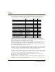
CLI Commands set set (ds1 card) adpcm map Use the set (ds1 card) adpcm map command to set voice compression map on the Quad DS1 ADPCM card. Syntax: set {adpcm_card-addr} adpcm {none|map1|map2|map3} Example: set 5 adpcm map1 {adpcm_card-addr} - The slot number (1-6) that contains the Quad DS1 ADPCM card. {none|map1|map2|map3} none map1, map2 or map3 DS0 Number 1 2 3 4 5 6 7 8 9 10 11 12 13 14 15 16 17 18 19 20 21 22 23 24 5-82 None will disable compression on the card. Default.
CLI Commands set set (ds3) Use the set (ds3) command to set up DS3 interfaces. The command specifies a range of interfaces and the setting to apply. Syntax: set {ds3-addr} {setting} Example: set a:1 framing m23 To set DS3 1 (port 1) on a DS3 Controller (slot A) to use M23 framing. {ds3-addr} DS3 address in the form {slot:port}. slot port A for the controller card, or 1-8 for service cards. Port number, range or all.
CLI Commands set frame framing gennum id line location id loopdetect payload portnum protect 5-84 Set the DS3 frame PMDL ID string Command syntax: set {ds3-addr} frame {"string"} {"string"} = transmission vendor’s identification, up to 10 characters, enclosed in quotes.
CLI Commands set reversion Set protection reversion on the DS3 off Disable protection reversion of loopback requests on Enable protection reversion of loopback requests threshold Set defect thresholds for a DS3. Defaults for all are 0. unit Axxius 800 - Release 2.
CLI Commands set set ethernet ip address Use the set ethernet ip address command to set the Ethernet address for the Axxius 800. Syntax: set ethernet ip address {ip-addr} [mask] Example: set ethernet ip address 172.26.100.25 255.255.255.0 {ip-addr} Set the IP address for the Axxius 800, using the form xxx.xxx.xxx.xxx, where xxx is a number from 0 to 255. [mask] Set the subnet mask, using the form xxx.xxx.xxx.xxx, where xxx is a number from 0 to 255. This is an optional setting.
CLI Commands set set (fxo) Use the set (fxo) command to setup one or all of the voice channels of an FXO card. The command specifies the list of voice channels within that card, and the setting to apply. Syntax: set {fxo-addr} {setting} Example: set 2:1 signal ls Set the FXO on slot 2, port 1 to signaling type loop start. {fxo-addr} List of voice channels to apply setting to, in the form {slot:port}.
CLI Commands set set (fxsPS or fxsPSM) Use the set (fxsPS or fxsPSM) command to setup voice channels of an Single Channel POTS card (FXS PS) or the POTS card with modem (FXS PSM). The command specifies the list of voice channels, and the setting to apply. Syntax: set {fxsPS-addr|fxsPSM-addr} {setting} Example: set 3:1 signal ls To set the port on slot 3 to Loop Start signaling. {fxsPS-addr|fxsPSM-addr} Voice channels to apply setting to, in the form of {slot:port}.
CLI Commands set set idle Use the set idle command to set the system-wide idle code sent on DS0s. Syntax: set idle {pattern} Example: set idle 0xff {pattern} A hexadecimal number with a range from 0x00 to 0xff. This number must be preceeded by 0x. set ip gateway Use the set ip gateway command to set the IP gateway address (also known as the default route) for the Axxius 800. The command specifies the numeric Internet Protocol (IP) address.
CLI Commands set set ipds0 Use the set ipds0 command to setup the DS0 management channel. Note: the DS0 selected as the DS0 management channel can only reside on the Controller T1. Syntax: set ipds0 {setting} [ds0-addr|ip-addr] Example: set ipds0 assign a:1:24 The example sets the DS0 management channel to slot A, port 1, channel 24.
CLI Commands set set key Use the set key command to enable a specific keyed feature. To acquire a feature key code, contact Carrier Access Customer Service. Currently, keyed features (if available) can be enabled on a Controller or a Router. Syntax: set [rtr_card-addr] key {"key-code"} Example: set 4 key "q0B8yma2IsSL+1BarY0u" [rtr_card-addr] The slot number (1-8) that contains the Router card. This optional parameter is used for router specific keyed features.
CLI Commands set set login support Use the set login support command to enable or disable the internal login accounts for Carrier Access Support personnel for the Controller and Router cards. Syntax: set login support {disable|enable} Example: set login support disable The example will prohibit logins via Carrier Access Support passwords. {disable|enable} disable enable Prohibit logins via Carrier Access Support passwords. Allow logins via Carrier Access Support passwords.
CLI Commands set set lsprotect enable/disable Use the set lsprotect enable/disable command to set the global enable or disable the Low Speed Protection options on the system. Syntax: set lsprotect {disable|enable} Example: set lsprotect disable {disable|enable} disable enable disable Low Speed Protection on the Axxius system enable Low Speed Protection on the Axxius system set lsprotect manual Use the set lsprotect manual command to set manual mode control for protected ports.
CLI Commands set set lsprotect nonrevertive Use the set lsprotect nonrevertive command to set low speed protected port(s) to non-revertive mode. When a port is in non-revertive mode and a failure occurs the port is switched to the protection port, and will remain there until manually reset. However, if the port becomes healthy again and another port has a failure the first port will revert, and the second port will then be protected.
CLI Commands set set lsprotect remove Use the set lsprotect remove command to remove port from protected mode. Syntax: set lsprotect {slot:port} remove Example: set lsprotect 5:2 remove Do you really want to do this? y *-Protected port(s) not removed since they were not previously assigned. Example: set lsprotect 5:2 remove > set lsprotect 5:2 remove Do you really want to do this? y OK {slot:port} The {slot:port} address of the protected port to be configured. slot port Axxius 800 - Release 2.
CLI Commands set set lsprotect revertive Use the set lsprotect revertive command to set low speed protected port(s) to revertive mode. When a port is set to revertive mode and a failure occurs the port is switched to the protection port. After 5 minutes, with no failures, the port reverts back. If there are 3 reverts in a 24 hour period the port is locked out and will remain with the protection port for 24 hours of no failures, or is manually reset.
CLI Commands set set (ocudp) baud Use the set (ocudp) baud command to configure the Baud Rate for OCU-DP ports. Syntax: set {ocudp-addr} baud {rate}[sw56|sw56cp] Example: set 3:2 baud 2400 Set the baud rate on port 2 to 2400, on the OCU-DP card in slot 3. {ocudp-addr} The {slot:port} address of the OCU-DP card you want to apply the changes to. slot port Slot number (1-8) where the OCU-DP is located Port number or range.
CLI Commands set set (ocudp) loopback Use the set (ocudp) loopback command to manually set OCU/CSU loopback tests. Syntax: set {ocudp-addr} loopback {csu|ocu} {loopdown|loopup} Example: set 3:2 loopback csu loopdown {ocudp-addr} The {slot:port} address of the OCU-DP card you want to apply the changes to. slot port Slot number (1-8) where the OCU-DP is located Port number or range.
CLI Commands set set (ocudp) loopdetect Use the set (ocudp) loopdetect to configure the OCU non-latching/latching loopback code detection. Syntax: set {ocudp-addr} loopdetect {csu|dsu|ocu} {llb|nllb} {disable|enable} Example: set 3:2 loopdetect csu llb enable {ocudp-addr} The {slot:port} address of the OCU-DP card to apply the changes to. slot port Slot number (1-8) where the OCU-DP is located Port number or range.
CLI Commands set set (ocudp) mvec Use the set (ocudp) mvec to set Majority Vote Error Correction (MVEC). Syntax: set {ocudp-addr} mvec {disable|enable} Example: set 3:2 mvec enable {ocudp-addr} The {slot:port} address of the OCU-DP card you want to apply the changes to. slot port Slot number (1-8) where the OCU-DP is located Port number or range. {disable|enable} disable* enable Disable the error correct. Disable is default.
CLI Commands set set (ocudp) selftest Use the set (ocudp) selftest to initiate the OCU-DP card to perform a self test. This request will display a message to wait 8 seconds before requesting selftest status with the status command. Syntax: set {ocudp-addr} selftest Example: set 3:2 selftest {ocudp-addr} The {slot:port} address of the OCU-DP card you want to apply the changes to. slot port Slot number (1-8) where the OCU-DP is located Port number or range.
CLI Commands set set (router) autologout Use the set (router) autologout command to set the period of time of inactivity after which the user will be automatically logged-out of a Telnet session. Syntax: set {rtr_card-addr} autologout {minutes} Example: set 3 autologout 0 The example will disable the auto-logout timer in the Router in slot 3. {rtr_card-addr} The slot number (1-8) that contains the Router card. {minutes} The minutes of inactivity before auto-logout occurs. Range is 0-255.
CLI Commands set set (router) dhcp Use the set (router) dhcp commands to configure the DHCP functions. set (router) dhcp disable Use the set (router) dhcp disable command to disable both DHCP server and DHCP relay functionality for the specified Router card. Syntax: set {rtr_card-addr} dhcp disable Example: set 3 dhcp disable The example will set the Router in slot 3 to disable DHCP. {rtr_card-addr} The slot number (1-8) that contains the Router card.
CLI Commands set set (router) dhcp server dnsserver Use the set (router) dhcp server dnsserver command to set the IP address of up to 4 DNS servers that the DHCP server will inform the clients of. Syntax: set {rtr_card-addr} dhcp server dnsserver {number} {ip-addr} Example: set 5 dhcp server dnsserver 4 122.104.33.220 The example will set the 4th DNS server address for the DHCP server on the Router card in slot 5 to 122.104.33.220 {rtr_card-addr} The slot number (1-8) that contains the Router card.
CLI Commands set set (router) dhcp server duration Use the set (router) dhcp server duration command to set the lease duration that the DHCP server applies to client assignments. Syntax: set {rtr_card-addr} dhcp server duration {hours:minutes} Example: set 5 dhcp server duration 3:45 The example set the lease duration for the DHCP server on the Router in slot 5 to 3 hours and 45 minutes. {rtr_card-addr} The slot number (1-8) that contains the Router card.
CLI Commands set set (router) dhcp server netbios nodetype Use the set (router) dhcp server netbios nodetype command to set the NetBIOS node type (see RFC 1001/1002) that the DHCP server provides to clients. Syntax: set {rtr_card-addr} dhcp server netbios nodetype {type-number} Example: set 5 dhcp server netbios nodetype 1 The example will set the NetBIOS node type to B-node. Note: DHCP server must first be enabled with the "startaddr" command. See set (router) dhcp server startaddr on page 5-107.
CLI Commands set set (router) dhcp server startaddr Use the set (router) dhcp server startaddr command to enable the DHCP server on the specified Router card. Syntax: set {rtr_card-addr} dhcp server startaddr {ip-addr} {count} Example: set 4 dhcp server startaddr 134.200.3.1 254 The example will set the TSR in slot 4 to enable the DHCP server with 254 address pool starting at 134.200.3.1. {rtr_card-addr} The slot number (1-8) that contains the Router card.
CLI Commands set set (router) dns Use the set (router) dns commands to set Domain Name Server (DNS) options. set (router) dns domain Use the set (router) dns domain command to set the default domain that the DNS resolver will add to any name queries that are not fully qualified. Syntax: set {rtr_card-addr} dns domain {domain-name"} Example: set 3 dns domain "mycompany.com" The example will set the default domain to "mycompany.com" for the Router in slot 3.
CLI Commands set set (router) dns resolver Use the set (router) dns resolver command to enable/disable use of DNS resolver to convert domain names to IP addresses. The DNS server address must be set before the DNS resolver can be enabled. Syntax: set {rtr_card-addr} dns resolver {disable|enable} Example: set 3 dns resolver disable The example will disable the DNS resolver for the Router in slot 3. {rtr_card-addr} The slot number (1-8) that contains the Router card.
CLI Commands set set (router) enhanced security Use the set (router) enhanced security command to enable or disable enhanced login security on the TSR. When enabled the user will not receive any login prompt or other output until the security password is typed. The security password is set via the set (router) password command. Syntax: set {rtr_card-addr} enhanced security {disable|enable} Example: set 5 enhanced security enable The example will enable the enhanced security on the Router card in slot 5.
CLI Commands set set (router) lmi poll Use the set (router) lmi poll command to specify the Local Management Interface (LMI) for the specified Router card. Syntax: set {rtr_card-addr} lmi poll {counter|interval} {value} Example: set 5 lmi poll counter 15 The example will configure LMI poll count to 15, on the Router card in slot 5. {rtr_card-addr} The slot number (1-8) that contains the Router card. {counter|interval} counter interval Set the LMI count.
CLI Commands set set (router) login prompt Use the set (router) login prompt command to enable/disable the login prompt on the specified Router card. Syntax: set {rtr_card-addr} login prompt {disable|enable} Example: set 1 login prompt enable The example will set the Router card to require a login with Telnets from the Controller. {rtr_card-addr} The slot number (1-8) that contains the Router card.
CLI Commands set set (router) ntp poll Use the set (router) ntp poll command to specify polling of the NTP server every defined number of seconds. Note: not operational in this release. Syntax: set {rtr_card-addr} ntp poll {seconds} Example: set 1 ntp poll 120 The example will Poll the Network Time Protocol server every 2 minutes, for the Router card in slot 1. {rtr_card-addr} The slot number (1-8) that contains the Router card. {seconds} The number of seconds between polls. Seconds range is 16 to 1024.
CLI Commands set set (router) ntp timezone Use the set (router) ntp timezone command to specify the timezone offset relative to GMT for this TSR. Note: not operational in this release. Syntax: set {rtr_card-addr} ntp timezone {hour-offset} [minute-offset] Example: set 1 ntp timezone -5 The example will specify the gateway time to be 5 hours from GMT (Greenwich Mean Time), which equates to Eastern Standard time, for the Router in slot 1. {rtr_card-addr} The slot number (1-8) that contains the Router card.
CLI Commands set set (router) port Use the set (router) port command to set port characteristics on a Terminal Server Router (TSR) card. set (router) port baudrate Use the set (router) port baudrate command to set the baud rate on a TSR port. Syntax: set {tsr_card-addr} port {port-number} baudrate {value} Example: set 5 port 2 baudrate 38400 The example will set the baud rate to 38400 on the second port on the TSR card in slot 5. {tsr_card-addr} The slot number (1-8) that contains the TSR card.
CLI Commands set set (router) port databits Use the set (router) port databits command to set the data bits on a TSR port. Syntax: set {tsr_card-addr} port {port-number} databits {5|6|7|8} Example: set 5 port 2 databits 6 The example will set the data bits to 6 on the port 2 on the TSR card in slot 5. {tsr_card-addr} The slot number (1-8) that contains the TSR card. {port-number} The port number (1-4) of the TSR card. {5|6|7|8} Allowable data bits. Note: If 1.
CLI Commands set set (router) port flowcontrol Use the set (router) port flowcontrol command to set the flow control on a TSR port. This command controls the transfer of messages or characters between two points in a data network to prevent congestion, or loss of data when the receiving device’s buffer begins to reach its capacity.
CLI Commands set set (router) port inactivity timer Use the set (router) port inactivity timer command to set the inactivity timeout for a RS-232 session. This setting can be issued when the card is physically strapped for Ethernet, bus has no effect. When this timer is set, the socket will be reset when no data is sent or received on the port for the number of minutes the timer is set to. This timer can be set for any application type, but is only active for termserv and rawtcp modes.
CLI Commands set set (router) port name Use the set (router) port name command to set define name for a TSR port. Syntax: set {tsr_card-addr} port {port-number} name {"name"} Example: set 5 port 2 name "portname" The example will set a port name on the second port on the TSR card in slot 5 to "portname". {tsr_card-addr} The slot number (1-8) that contains the TSR card. {port-number} The port number (1-4) of the TSR card. {name} Port identifier, with up to 15 characters, enclosed in quotes.
CLI Commands set set (router) port passive Use the set (router) port passive command to set the TSR port to passive. This command will terminate any active telnet connection on this interface and will reinitialize its associated TCP socket. Syntax: set {tsr_card-addr} port {port-number} passive Example: set 1 port 2 passive Do you wish to do this (y/n)? {tsr_card-addr} The slot number (1-8) that contains the TSR card. {port-number} The port number (1-4) of the TSR card.
CLI Commands set set (router) port prompt Use the set (router) port prompt command to set the authentication prompt on a TSR port. Syntax: set {tsr_card-addr} port {port-number} prompt {disable|enable} Example: set 1 port 2 prompt enable This command will enable the authentication prompt for port 2 on the TSR card in slot 1. {tsr_card-addr} The slot number (1-8) that contains the TSR card. {port-number} The port number (1-4) of the TSR card.
CLI Commands set set (router) port stopbits Use the set (router) port stopbits command to set the number of stop bits on a TSR port. The stop bit is an interval at the end of each Asynchronous Character that allows the receiving computer to pause before the start of the next character. Syntax: set {tsr_card-addr} port {port-number} stopbits {1|1.5|2} Example: set 5 port 2 stopbits 1 The example will set the number of stop bits on the second port on the TSR card in slot 5 to 1.
CLI Commands set set (router) port tbos map display Use the set (router) port tbos map display command to set a TBOS (Telemetry Byte Oriented Serial) display map value for one of the eight TBOS display available for monitoring equipment. This setting can be issued when the card is physically strapped for Ethernet, but has no effect. This setting can be done for any application type but is only used when type is set to TBOS. Note: this command is only available on a TSR card that has TBOS feature enabled.
CLI Commands set set (router) port type Use the set (router) port type command to set the application being used for a RS-232 (serial) port. This setting can be issued when the card is physically strapped for Ethernet, but has no effect. This command applies to the TSR only. Syntax: set {tsr_card-addr} port {port-number} type {termserv|rawtcp|tbos} Example: set 5 port 2 type tbos {tsr_card-addr} - The slot number (1-8) that contains the TSR card. {port-number} - The port number (1-4) of the TSR card.
CLI Commands set set (router) ppp auth Use the set (router) ppp auth command to configure the PPP (Point-to-Point Protocol) authentication on the specified Router card. set (router) ppp auth byremote protocol Syntax: set {rtr_card-addr} ppp auth byremote protocol {chap|none|pap} Example: set 5 ppp auth byremote protocol none The example will set the Router in slot 5 to not allow PPP authentication of this Axxius by the remote PPP device. {rtr_card-addr} The slot number (1-8) that contains the Router card.
CLI Commands set set (router) ppp auth byremote user Syntax: set {rtr_card-addr} ppp auth byremote user {profilename|"protocol-name"} Example: set 5 ppp auth byremote user profilename The example will set the PPP authentication user name for the Router in slot 5 to equal the profile name. Note: A set (router) ppp auth byremote protocol command must be completed before this command can be implemented. {rtr_card-addr} The slot number (1-8) that contains the Router card.
CLI Commands set set (router) ppp security Use the set (router) ppp security command to set up the local external security server, that the Router will use to authenticate remote PPP devices. set (router) ppp security address Syntax: set {rtr_card-addr} ppp security address {ip-addr} Example: set 5 ppp security address 10.1.1.1 The example will set external security server address to 10.1.1.1, for the Router in slot 5.
CLI Commands set set (router) ppp security server Syntax: set {rtr_card-addr} ppp security server {none|radius|tacacs} Example: set 5 ppp security server none The example will set the Router in slot 5 to not use an external security server to authenticate remote PPP devices. {rtr_card-addr} The slot number (1-8) that contains the Router card. {none|radius|tacacs} none radius tacacs 5-128 Do not use an external security server to authenticate remote PPP devices (default).
CLI Commands set set (router) proxy Use the set (router) proxy command to enable/disable proxy ARP mode on the Router. This command will add an IP interface between the Controller and the Router over the backplane. In this way the Controller can be accessed by IP hosts over the Router’s LAN/WAN interfaces without using the Controller’s physical Ethernet interface. Syntax: set {rtr_card-addr} proxy {disable|enable} [ip-addr] [mask|bits] Example: set ethernet ip address 10.0.0.1 255.0.0.
CLI Commands set There are numerous cases of IP address assignments for the proxy and each case causes slightly different behavior: Proxy address is in the same subnet as the Controller LAN address. If the Controller Ethernet IP address and the proxy IP address are in the same subnet, either since both addresses are the same or they fall into the same subnet based on address and mask, the Controller will attempt to use the Ethernet interface to send packets to other hosts in that subnet.
CLI Commands set set (router) reboot Use the set (router) reboot command to set automatic reboot after an upload of code or configuration file. Syntax: set {rtr_card-addr} reboot {code|config} {disable|enable} Example: set 5 reboot both disable Disable automatic reboot after upload for the Router in slot 5. {rtr_card-addr} The slot number (1-8) that contains the Router card.
CLI Commands set set (router) snmp Use the set (router) snmp command to set the SNMP contact, location and name on the specified Router card. set (router) snmp contact Use the set (router) snmp contact command to set the value of sysContact on the specified Router card. Syntax: set {rtr_card-addr} snmp contact {"contact-name"} Example: set 1 snmp contact "John Doe" The example will set the value of sysContact on the Router card in slot 1 to "John Doe".
CLI Commands set set (router) snmp name Use the set (router) snmp name command to set the value of sysName on the specified Router card. Syntax: set {rtr_card-addr} snmp name {"system-name"} Example: set 1 snmp name "AxxiusRouters" The example will set the value of sysName on the TSR card in slot 1 to "AxxiusRouters". {rtr_card-addr} The slot number (1-8) that contains the Router card. {"system-name"} The value of sysName, with a maximum of 64 ASCII characters. Name must be enclosed in quotes.
CLI Commands set set (router) stp Use the set (router) stp commands to configure the Spanning Tree Protocol on the Router. Note: Enter {slot} only, if {slot:port} is entered the command will be directed to the Router LAN and not the Router Card. set (router) stp bridge forwarddelay Use the set (router) stp bridge forwarddelay command to configure Spanning Tree bridge forward delay value for the bridge.
CLI Commands set set (router) stp bridge maxage Use the set (router) stp bridge maxage command to configure Spanning Tree maximum age value for the bridge. The bridge max age value specifies the maximum age of received protocol information before it is discarded. Syntax: set {rtr_card-addr} stp maxage {value} Example: set 3 stp bridge maxage 15 The example will set the Spanning Tree bridge max age to 15 seconds, on the Router in slot 3. {rtr_card-addr} The slot number (1-8) that contains the Router card.
CLI Commands set set (router) stp enable/disable Use the set (router) stp enable/disable command to enable and disable Spanning Tree Protocol on the Router. Syntax: set {rtr_card-addr} stp {disable|enable} Example: set 3 stp enable The example will enable Spanning Tree on the Router in slot 3. {rtr_card-addr} The slot number (1-8) that contains the Router card. Note: Enter {slot} only. If {slot:port} is entered the command will be directed to the Router LAN and not the Router Card.
CLI Commands set set (router) syslog Use the set (router) syslog commands to configure the Router to send alarm and event messages to a Syslog server. set (router) syslog enable/disable Use the set (router) syslog enable/disable command to enable and disable sending alarm and event messages to an external Syslog server from the Router.
CLI Commands set set (router) syslog level Use the set (router) syslog level command to set the Syslog severity level. Events of all severity levels lower in number (more severe) will be sent to the Syslog server. Syntax: set {rtr_card-addr} syslog level {severity} Example: set 3 syslog level 4 The example will set the Syslog severity level to 4, on the Router card in slot 3. {rtr_card-addr} The slot number (1-8) that contains the Router card. {severity} The severity threshold level can range from 0 to 7.
CLI Commands set set (router-lan) filter forward Use the set (router-lan) filter forward command to specify the forwarding mode for Layer 2 filters on the LAN interface. Syntax: set {rtr_lan-addr} filter forward {matching|nontmatching} Example: set 3:1 filter forward notmatching {rtr_lan-addr} The Router address is in the form {slot:port} or {slot "profile-name"}. slot port "profile-name" The slot number (1-8) that contains the Router card. Port number of the Router.
CLI Commands set set (router-lan) framing Use the set (router-lan) framing command to specify which Ethernet frame types are supported on the LAN interface. Syntax: set {rtr_lan-addr} framing {ipx|other} {ieee8022|ieee8023|ethii|snap} {disable|enable} Example: set 3:1 framing ipx ieee8022 enable The example will enable the 802.2 frame type for IPX packets on the LAN of the Router card in slot 3. {rtr_lan-addr} The Router address is in the form {slot:port} or {slot "profile-name"}.
CLI Commands set set (router-lan) gateway Use the set (router-lan) gateway command to specify a default IP gateway for the specified LAN interface. If there is no static network entry to 0.0.0.0, then this address is used as the default gateway for packets with no explicit route. Syntax: set {rtr_lan-addr} gateway {ip-addr} Example: set 3:1 gateway 192.168.201.144 The example will set the local LAN interface on slot 3 to use a default gateway at IP address 192.168.201.144.
CLI Commands set set (router-lan) ip address Use the set (router-lan) ip address command to specify an IP address for the specified LAN interface. When first installed the Router card’s LAN interface has a default IP address of 10.0.0.1 with subnet mask of 255.0.0.0. Syntax: set {rtr_lan-addr} ip address {ip-addr} [mask] Example: set 3:1 ip address 192.168.202.244 255.255.255.0 The example will set the local LAN interface on slot 3 to IP address 192.168.202.244, with a subnet mask of 255.255.255.0.
CLI Commands set set (router-lan) ipx network Use the set (router-lan) ipx network command to specify IPX network numbers for the four IPX LAN frame types. This enables the Axxius to Router IPX to Remote (WAN) networks, even if an IPX server does not exist on the local LAN. Typically, the Axxius will learn its external network number.
CLI Commands set set (router-lan) phy Use the set (router-lan) phy command to specify the Ethernet PHY (physical specifications) speed and mode. NOTE: It is highly recommended that this setting be left at autonegotiation. Connecting Ethernet devices with incompatible setting can lead to severe network performance degradation, increased collisions, late collisions, CRC errors, and undetected data corruption.
CLI Commands set set (router-lan) rip Use the set (router-lan) rip commands to specify RIP for the specified LAN interface. set (router-lan) rip ip Use the set (router-lan) rip ip command to specify the IP RIP for the specified LAN interface. Syntax: set {rtr_lan-addr} rip ip {both|neither|recv|send} Example: set 2:1 rip ip send The example will set RIP on the local LAN interface on slot 2 to send. {rtr_lan-addr} The Router address is in the form {slot:port} or {slot "profile-name"}.
CLI Commands set set (router-lan) rip ipx Use the set (router-lan) rip ipx command to specify the IPX RIP and SAP for the specified LAN interface. Syntax: set {rtr_lan-addr} rip ipx {both|neither|recv|send} Example: set 2:1 rip ipx send The example will set RIP and SAP on the local LAN interface on slot 2 to send. {rtr_lan-addr} The Router address is in the form {slot:port} or {slot "profile-name"}. slot port "profile-name" The slot number (1-8) that contains the Router card. Port number of the Router.
CLI Commands set set (router-lan) stp Use the set (router-lan) stp commands to configure the Spanning Tree Protocol on this interface. set (router-lan) stp enable/disable Use the set (router-lan) stp enable/disable command to enable/disable Spanning Tree Protocol on this interface. To enable STP on an interface it must be enabled globally with the set (router) stp enable command.
CLI Commands set set (router-lan) stp port cost Use the set (router-lan) stp port cost command to configure Spanning Tree path cost value for this bridge port. Syntax: set {rtr_lan-addr} stp port cost {port-cost-value} Example: set 3:1 stp port cost 100 Sets the Spanning Tree port cost value at 100, on the Router in slot 3. {rtr_lan-addr} The Router address is in the form {slot:port} or {slot "profile-name"}. slot port "profile-name" Slot number (1-8) that contains the Router card.
CLI Commands set set (router-lan) up/down Use the set (router-lan) up/down command to set the specified LAN interface up or down. When the Router port is set down, a link failure will not cause an alarm. This can be used to eliminate alarms from Router ports that are not in-use. When the Router port is set up, a link failure on the Ethernet port will cause an alarm to be reported to the Axxius 800.
CLI Commands set set (router-trunk) encapsulation Use the set (router-trunk) encapsulation command to specify the encapsulation to use on the TSR interface. Syntax: set {rtr_trunk-addr} encapsulation {setting} Example: set 2:1:5 encapsulation pppofr The example will configure encapsulation on the Router card in slot 2, port 1, trunk 5 to PPP over.
CLI Commands set set (router-trunk) speed Use the set (router-trunk) speed command to specify the data speed for each DS0 in the given trunk. This command takes effect upon transition of the trunk to active. This command applies to the TSR card only. Syntax: set {tsr-trunk-addr} speed {56|64} Example: set 3:1:23 speed 56 The example will set the data speed of trunk 23 in the TSR in slot 3 to 56 Kbps.
CLI Commands set set (router-wan) dlci Use the set (router-wan) dlci command to set the DLCI (Data Link Connection Identifier) for a specified WAN interface. Syntax: set {rtr_card-addr} {"wan-name"} dlci {value} Example: set 1 "LosAngeles" dlci 16 The example will set the WAN interface named "LosAngeles" on the Router card in slot 1 to use DLCI value 16. {rtr_card-addr} The slot number (1-8) that contains the Router card. {"wan-name"} The WAN interface to modify. The name must be enclosed in quotes.
CLI Commands set set (router-wan) gre Use the set (router-wan) gre command to configure Generic Routing Encapsulation tunneling for a specified WAN interface. set (router-wan) gre address Use the set (router-wan) gre address command to configure the IP addresses for GRE tunneling for a specified WAN interface. Syntax: set {rtr_card-addr} {"wan-name"} gre address {local_ip-addr} [remote-ip-addr] ["tunnel-name"] Example: set 3 "LosAngeles" gre address 10.0.0.0 20.0.0.
CLI Commands set set (router-wan) gre ip Use the set (router-wan) gre ip command to configure the GRE tunneling of the IP protocol for a specified WAN interface. Syntax: set {rtr_card-addr} {"wan-name"} gre ip {all|bynetwork|disable} Example: set 3 "LosAngeles" gre ip all The example will set the WAN interface "LosAngeles" in slot 3, to pass all packets through a GRE tunnel. {rtr_card-addr} The slot number (1-8) that contains the Router card. {"wan-name"} The WAN interface to modify.
CLI Commands set set (router-wan) ip Use the set (router-wan) ip command to set the IP traffic handling on the WAN interface. Syntax: set {rtr_card-addr} {"wan-name"} ip {block|bridge|route} Example: set 1 "LosAngeles" ip route Sets the WAN interface named "LosAngeles" on the Router in slot 1 to route IP. {rtr_card-addr} The slot number (1-8) that contains the Router card. {"wan-name"} The WAN interface to modify. The name must be enclosed in quotes.
CLI Commands set set (router-wan) ipx Use the set (router-wan) ipx command to set the IPX traffic handling on the specified WAN interface. Syntax: set {rtr_card-addr} {"wan-name"} ipx {setting} Example: set 1 "LosAngeles" ipx bridge The example will set the WAN interface named "LosAngeles" in slot 1, to bridge IPX. {rtr_card-addr} The slot number (1-8) that contains the Router card. {"wan-name"} The WAN interface to modify. The name must be enclosed in quotes.
CLI Commands set set (router-wan) nat Use the set (router-wan) nat commands to configure Network Address Translation (NAT) on a specified WAN interface. set (router-wan) nat address Use the set (router-wan) nat address command to configure Network Address Translation (NAT) public addresses for a specified WAN interface. Syntax: set {rtr_card-addr} {"wan-name"} nat address {assigned|ip-addr} [count] Example: set 1 "LosAngeles" nat address 201.17.172.
CLI Commands set set (router-wan) nat enable/disable Use the set (router-wan) nat command to enable and disable Network Address Translation (NAT) on a specified WAN interface. Syntax: set {rtr_card-addr} {"wan-name"} nat {disable|enable} Example: set 1 "LosAngeles" nat enable The example will set the WAN interface named "LosAngeles" on the Router card in slot 1 to enable NAT mapping. {rtr_card-addr} The slot number (1-8) that contains the Router card. {"wan-name"} The WAN interface to modify.
CLI Commands set set (router-wan) other Use the set (router-wan) other command to set the traffic handling of protocols other than IP or IPX on the specified WAN interface. Syntax: set {rtr_card-addr} {"wan-name"} other {block|bridge} Example: set 1 "LosAngeles" other bridge The example will set the WAN interface named "LosAngeles" in slot 1, to bridge other protocols. {rtr_card-addr} The slot number (1-8) that contains the Router card. {"wan-name"} The WAN interface to modify.
CLI Commands set set (router-wan) ppp Use the set (router) ppp command to configure the PPP (Point-to-Point Protocol) on the specified Router card. set (router-wan) ppp auth ofremote user Use the set (router-wan) ppp auth ofremote user command to set the CHAP or PAP name by which a remote PPP device is authenticated by this Axxius.
CLI Commands set set (router-wan) ppp compression Use the set (router-wan) ppp compression command to configure the PPP compression with the remote PPP device. Syntax: set {rtr_card-addr} {"wan-name"} ppp compression {setting} Example: set 5 "LosAngeles" ppp compression enable The example will set PPP to attempt to negotiate PPP compression on the WAN interface named "LosAngeles" in slot 1. {rtr_card-addr} The slot number (1-8) that contains the Router card. {"wan-name"} The WAN interface to modify.
CLI Commands set set (router-wan) rip Use the set (router-wan) rip commands to set the type of RIP updates on the WAN interface. set (router-wan) rip ip updates Use the set (router-wan) rip ip updates command to set the type of RIP updates on the specified WAN interface.
CLI Commands set set (router-wan) stp Use the set (router-wan) stp commands to configure the Spanning Tree Protocol on the specified WAN interface. set (router-wan) stp enable/disable Use the set (router-wan) stp enable/disable command to enable and disable Spanning Tree Protocol on this interface. To enable Spanning Tree on an interface it must first be enabled globally with the set (router) stp enable command and the WAN must be set to bridge the IP protocol.
CLI Commands set set (router-wan) stp port cost Use the set (router-wan) stp port cost command to configure Spanning Tree path cost value for this bridge port. Syntax: set {rtr_card-addr} {"wan-name"} stp port cost {port-cost-value} Example: set 3 stp port cost 650 The example sets the Spanning Tree port cost value at 650, on the Router card in slot 3. {rtr_card-addr} The slot number (1-8) that contains the Router card. {"wan-name"} The WAN interface to modify. The name must be enclosed in quotes.
CLI Commands set set (router-wan) trunk Use the set (router-wan) trunk command to configure the trunk port or multilink group for a specified WAN interface. If the trunk encapsulation is subsequently changed, this trunk assignment is reset to 0. Syntax: set {rtr_card-addr} {"wan-name"} trunk [multilink-group] {number} Example: set 1 "LosAngeles" trunk 3 The example will set the WAN interface named "LosAngeles" on the Router card in slot 1 to be mapped to trunk 3.
CLI Commands set set screen Use the set screen command to set the height of the scrolling output screen, in number of lines. For example, if the screen height is set to 40 lines, the Command Line Interface (CLI) will print the maximum of 40 lines of a long output before pausing. To set the screen to scroll without pausing, set the screen height to 0. Syntax: set screen {screen-height|off} Where screen-height is the number of lines in the scrolling output screen. 5-166 Axxius 800 - Release 2.
CLI Commands set set snmp Use the set snmp command to set the Simple Network Management Protocol (SNMP) MIB-II System Group objects. Syntax: set snmp {setting} {"string"} Where {setting} is as below, and {string} is its value. Example: set snmp name "Axxius 1" To set the SNMP system name to "Axxius 1" Example: set snmp nms 2 192.168.3.50 Set the second SNMP NMS IP address to 192.168.3.
CLI Commands set set time Use the set time command to set the time. Syntax: set time {hh:mm:ss} Example: set time 12:00:00 The example will set the time to 12 noon. {hh:mm:ss} Where hh:mm:ss is the time in hours, minutes, and seconds, using a 24-hour clock. 5-168 Axxius 800 - Release 2.
CLI Commands set set user Use the set user command to modify attributes for a specific user that have been created with the add user command. set user level Use the set user level command to set the user access level. Syntax: set user {"user-name"} level {1|2|3} Example: set user "paul" level 2 {"user-name"} The user-name is a user ID to add to the system. Text is a single word, with no blank spaces and must be enclosed in quotes. {1| 2| 3} Sets the level of access.
CLI Commands set set (v35) Use the set (v35) command to setup V.35 ports. The command specifies the range of channels within that card, and the setting to apply. Syntax: set {v35-addr} {setting} Example: set 6:1 rxclk normal To set port 1 (v.35) on slot 6 to no inversion on the receive clock {v35-addr} In the form of {slot:port}. slot port Slot number (1-8) of the Axxius chassis where the V.35 card is located Port number or range.
CLI Commands set speed txclkinv Axxius 800 - Release 2.2 Set the data rate for each DS0 to which a V.
CLI Commands set set (v54) Use the set (v54) command to setup V.54 Loopback Test Parameters. The command specifies the range of channels within that card, and the setting to apply. Syntax: set {v54-addr} v54 {setting} [off|on] [n] [nnn] Example: set 6:1 v54 equipment clear The example will clear the loop test counter on the V.54 card in slot 6, port 1. {v54-addr} In the form of {slot:port}. slot port Slot number (1-8) of the Axxius chassis where the V.35/54 card is located Port number or range.
CLI Commands set pattern Syntax: set{v54-addr} v54 equipment pattern {n} Set V.54 test pattern n is from the following: 0 = QRSS pattern (default) 1 = 2047 pattern 2 = 215 -1 pattern 3 = 220 -1 pattern (QRSS with no bit stuffing) prepcnt network address Syntax: set {v54-addr} v54 equipment prepcnt {nnn} Set V.54 Rx prep-pattern count {nnn} nnn = the number of times that the preparatory pattern must be received to be recognized. Set the V.54 Network loop address.
CLI Commands set set verification Use the set verification command to enable or disable verification prompts. Syntax: set verification {off|on} Example: set verification off The example will cause yes/no verification messages to be suppressed. {off|on} off on 5-174 Turn yes/no verification prompts off. Turn yes/no verification prompts on. Axxius 800 - Release 2.
CLI Commands show show The following show commands are linked to a detailed description of each command.
CLI Commands show show (adpcm) Use the show (adpcm) command to display the settings for the ADPCM card. Syntax: show {adpcm-addr} Example: > show 6:1 show 6:1 SLOT 6: Settings for DS1 1: Circuit ID: Up/Down: Framing: Line Coding: Line Build Out: (CSU 0dB) Loop Code Detection: Loopback: FDL Type: ADPCM: ADPCM Map: CAC DS1# 6:1 UP ESF B8ZS DSX-1 EQUALIZATION FOR 0-133 ft. ON OFF None Enabled 2 Performance Threshold Settings unavailable seconds: severely errored seconds: errored seconds: sev.
CLI Commands show show autoexit Use the show autoexit command to display whether autoexit is on or off. If on, the time-out period is displayed. Syntax: show autoexit Example: > show autoexit Autoexit is off. show (bri) Use the show (bri) command to display settings for BRIs. Syntax: show {bri-addr} Example: > show 5:1 The example will display the settings for port 1 (BRI) on slot 5.
CLI Commands show show cclabels The show cclabels command displays all user defined DS0 cross-connect labels. Syntax: show cclabels Example: show cclabels > show cclabels Current DS0 Connection Labels: ---------------------------’label1’ ’label2’ ’label3’ ’test’ ---------’label4’ ---------’V35label’ show clock The show clock command displays the primary and secondary clocks. Syntax: show clock Example: show clock This example will display the primary and secondary clock source.
CLI Commands show show connect The show connect command displays the static connections for channels and ports. Syntax: show connect {slot|slot:port|slot:port:channel| slot:port:channel:sub-channel} Example: show connect a:1:1-4 From A:01:01 A:01:02 A:01:03 A:01:04 Desc DATA DS0 DATA DS0 DATA DS0 DATA DS0 Desc To Comment {slot|slot:port|slot:port:channel|slot:port:channel|sub-channel} slot port channel sub-channel Axxius 800 - Release 2.
CLI Commands show show connect adpcm The show connect adpcm command displays the connections for the ADPCM port.
CLI Commands show show (ds0) The show (ds0) command displays settings for DS0s. Syntax: show {ds0-addr} Example: show a:2:1-2 In the following example, the show (ds0) command has queried slot A (Controller card), port 2, channels 1 through 2.
CLI Commands show show (ds1) The show (ds1) command displays settings for DS1s. Syntax: show {ds1-addr} Example: show 1:1 SLOT A: Settings for DS1 1: Circuit ID: CAC DS1# A:1 Up/Down: DOWN Framing: ESF Line Coding: B8ZS Line Build Out: DSX-1 EQUALIZATION FOR 0-133 ft.(CSU 0dB) Loop Code Detection:ON Loopback: OFF FDL Type: None AIS Forwarding: Enabled AIS DS1 List: 2:1, 3:1, 4:1, 5:1 Performance Threshold Settings unavailable seconds: severely errored seconds: errored seconds: sev.
CLI Commands show show (ds3) The show (ds3) command displays the current settings for a DS3.
CLI Commands show {ds3-addr} In the form of {slot:port}. slot port A for the controller card (DS3) Port number or range. show ethernet The show ethernet command displays Ethernet and IP settings. Example: show ethernet > show ethernet IP Address and Mask: IP Address of the Gateway: MAC Address: 198.162.3.196 255.255.255.0 192.168.3.202 00:E0:97:00:A9:33 show external alarms The show external alarms command displays the external alarm setting.
CLI Commands show show (fxo) The show (fxo) command displays the settings for FXOs. Syntax: show {fxo-addr} Example: show 7:1 The example shows settings for port 1 on the FXO card i slot 7. > show 7:1 SLOT 7: Settings for FXO: Type: Signaling: RxGain: TxGain: channel 1: VOICE LS -6 dB -3 dB {fxo-addr} In the form of {slot:port}. slot port Axxius 800 - Release 2.2 Location of the FXO card, slot 1-8. Port number, range or "all".
CLI Commands show show (fxsPS or fxsPSM) The show (fxsPS or fxsPSM) command displays the settings for the Single Channel POTS card without modem (FXS PS) or with modem (FXS PSM). Syntax: show {fxsPS-addr|fxsPSM-addr} Example: show 8:1 The example shows settings for the FXS PS card in slot 8. > show 8:1 SLOT 8: Settings for FXS: Type: Signaling: RxGain: TxGain: channel 1: VOICE LS -6 dB -3 dB {fxsPS-addr|fxsPSM-addr} In the form of {slot:port}.
CLI Commands show show image The show image command displays the application images stored in the Controller or Router. Syntax: show [rtr_card-addr] image Example: show image > show image App. Image: Ver=7.0 Fri Aug 29 06:40:42 2003 - ACTIVE App. Image: Ver=7.0 Thu Aug 14 13:01:18 2003 - BACKUP Example: show 5 image > show 5 image SLOT 5: App. Image: Ver=1.30K App. Image: Ver=1.
CLI Commands show show impedance The show impedance command displays the impedance settings for FXS 5G card. Syntax: show impedance Example: show impedance Index 1 2 3 4 5 6 + + + + + + Impedance (.110µF || (.047µF || (.072µF || (.100µF || (.137µF || (.115µF || 120 150 150 200 215 220 Ohms Ohms Ohms Ohms Ohms Ohms 820 510 830 680 1k 820 Ohms) Ohms) Ohms) Ohms) Ohms) Ohms) 7 8 9 10 11 12 13 220 270 300 370 400 400 600 Ohms Ohms Ohms Ohms Ohms Ohms Ohms + + + + + + (.120µF (.120µF (.220µF (.
CLI Commands show show ip The show ip command displays the IP Address information for the Axxius 800. Syntax: show ip Example: show ip IP Address and Mask: IP Address of the Gateway: 192.168.3.193 192.168.3.202 255.255.255.0 OK show ipds0 The show ipds0 command displays the settings for the DS0 management channel. Syntax: show ipds0 Example: show ipsd0 Administrative state: DS0 Selected: IP Address and Mask: DOWN a:1:1 192.168.210.1 255.255.255.
CLI Commands show show lsprotect The show lsprotect command displays the low speed protection information.
CLI Commands show show ntp The show ntp command displays settings for Network Time Protocol. Syntax: show ntp Example: show ntp NTP Settings: NTP: Disabled NTP Server Address: 0.0.0.0 NTP Polling Interval (seconds): 16 NTP Timezone (offset from GMT): 0 hours 0 minutes show (ocudp) Use the show (ocudp) to display baud, loopdetect, error correction, switched and enhanced switched service and secondary channel provisioning.
CLI Commands show show radius The show radius command displays the RADIUS configuration settings for the Controller. Syntax: show radius Example: show radius RADIUS Configuration Parameters: Authentication: NAS Identifier: Retry count: Timeout (sec): Server(1) : Server(2) : Server(3) : 5-192 disabled 3 3 UNUSED UNUSED UNUSED Axxius 800 - Release 2.
CLI Commands show show (router) The show (router) command displays the settings for the Router card.
CLI Commands show Spanning Tree Protocol Settings for Router: Spanning Tree: Disabled Syslog Settings for Router: Syslog: Disabled TFTP Upload/Download User Settings for Router: Reboot After Code is Loaded: Yes Reboot After Configuration is Loaded: Yes IP Address Total: 0 Client Site Upload/Download Code Config LAN Profile Name for Router: LocalUnit 10.0.0.1 WAN Profile Name(s) for Router: RemoteUnit Unnumbered {rtr_card-addr} The slot number (1-8) that contains the Router card.
CLI Commands show show (router) dhcp The show (router) dhcp command displays the current DHCP settings for the Router card. Syntax: show {rtr_card-addr} dhcp Example: show 5 dhcp The following 3 examples, shows there is different information is displayed depending on the settings. > show 5 dhcp SLOT 5: DHCP Server/BOOTP Relay Agent Settings for Router: DHCP: Disabled > show 5 dhcp SLOT 3: DHCP Server/BOOTP Relay Agent Settings for Router: DHCP/BOOTP Relay Agent: Enabled BOOTP Relay Servers: 192.168.1.
CLI Commands show show (router) dns The show (router) dns command displays the current DNS setup for the Router card. Syntax: show {rtr_card-addr} dns Example: show 3 dns > show 3 dns SLOT 3: DNS Settings: DNS Resolver: DNS Server 1 IP Address: DNS Server 2 IP Address: DNS Host Name: DNS Default Domain: Disabled 0.0.0.0 0.0.0.0 domaintest DNS Static Host List: Total: 0 {rtr_card-addr} The slot number (1-8) that contains the Router card.
CLI Commands show show (router) lmi The show (router) lmi command displays the current Local Management Interface (LMI) settings for the Router card. Syntax: show {rtr_card-addr} lmi Example: show 5 lmi The example shows the LMI settings for the Router card in slot 5. > show 5 lmi SLOT 5: LMI Settings for Router: LMI: Disabled {rtr_card-addr} The slot number (1-8) that contains the Router card. show (router) login The show (router) login command displays the Router login configuration.
CLI Commands show show (router) ntp The show (router) ntp command displays settings for NTP options. Syntax: show {rtr_card-addr} ntp Example: show 4 ntp The example shows the NTP options for the Router card in slot 4. > show 4 ntp SLOT 4: NTP Settings for QTSR: NTP: Disabled NTP Server: 0.0.0.0 NTP Interval (seconds):120 NTP Timezone (offset from GMT):0 hours 0 minutes {rtr_card-addr} The slot number (1-8) that contains the Router card. 5-198 Axxius 800 - Release 2.
CLI Commands show show (router) port The show (router) port command displays the current TSR ports configuration. This command applies to the Terminal Server Router card only. Syntax: show {tsr_card-addr} port Example: show 1 port SLOT 1: Port Profiles for Terminal Server Router: Port 1 Name: none Type: RS-232 Asynchronous Settings Socket: 10.10.11.1:23 TCP Baud Rate 9600 Data Bits 8 Stop Bits 1 No Parity No Flowcontrol Port 2 Name: none Type: RS-232 Asynchronous Settings Socket: 10.10.11.
CLI Commands show show (router) ppp The show (router) ppp command displays the current Local PPP (Point-to-Point Protocol) authentication and security settings for the Router card. Syntax: show {rtr_card-addr} ppp Example: show 5 ppp > show 5 ppp SLOT 5: PPP Authentication/Security Settings for Router: Authentication by Remote: Protocol: CHAP Secret: public User ID: Local Profile Name Authentication of Remote: Protocol: CHAP Local Security Server: Type: Radius IP Address: 168.0.0.
CLI Commands show show (router) rip The show (router) rip command displays the current RIP settings for the Router card. Syntax: show {rtr_card-addr} rip Example: show 5 rip SLOT 5: RIP Settings for Router: RIP Mode Receive: RIP2 RIP Mode Send: Rip2 {rtr_card-addr} The slot number (1-8) that contains the Router card. show (router) snmp The show (router) snmp command displays the current SNMP settings for the specified Router card.
CLI Commands show show (router) stp The show (router) stp command displays the current Spanning Tree Protocol settings for the specified Router card. Syntax: show {rtr_card-addr} stp Example: show 5 stp > show 5 stp SLOT 5: Spanning Tree Protocol Settings for Router: Spanning Tree: Enabled Bridge Hello Time: 2 seconds Bridge Max Age: 20 seconds Bridge Forward Delay: 15 seconds Bridge Priority: 32768 {rtr_card-addr} The slot number (1-8) that contains the Router card.
CLI Commands show show (router) uploaduser The show uploaduser command displays the current list of users allowed to upload and download configuration and code files.
CLI Commands show show (router-lan) The show (router-lan) command displays the settings for the router card. Syntax: show {rtr_lan-addr} Example: show 3:1 > show 3:1 SLOT 3: Settings for TSR LAN 1: Profile Name: Up/Down: Proxy: Physical link: MAC Address: IP Settings: IP Address and Mask: Default Router: Enabled Frame Types: RIP Direction: LocalUnit UP Disabled Automatic 00:E0:97:FF:FF:FE 10.0.0.1 0.0.0.0 Ethernet II Neither 255.0.0.0 IPX Settings: Enabled Frame Types: Ethernet II,IEEE 802.2,IEEE 802.
CLI Commands show Total: 0 Static MAC Address Settings for LocalUnit: Total: 0 LAN Filters Enabled for LocalUnit: Forward Mode: Forward ALL Frames NOT Matching Filters Filter Type Total: 0 Source/Dest Filter Name LAN MAC Address Filters Defined for LocalUnit: Total: 0 LAN Protocol Filters Defined for LocalUnit: Total: 0 LAN Custom Filters Enabled Defined for LocalUnit: Total: 0 Settings for TSR WAN RemoteUnit: State: Enabled IP Settings: Mode: Route WAN Network Updates: Never GRE Tunneling: Disabled IPX
CLI Commands show show (router-lan) filter The show (router-lan) filter command displays the current LAN Layer 2 data filters applied to the LAN on the specified Router card.
CLI Commands show {rtr_lan-addr} The Router address is in the form {slot:port} or {slot "profile-name"} slot port "profile-name" The slot number (1-8) that contains the Router card. Port number of the Router. The profile name for the Router interface. Name must be enclosed in quotes, with a maximum length of 11 characters. [address|custom|protocol|all] This setting will display the defined filter types of the specified filters. address custom protocol all Axxius 800 - Release 2.
CLI Commands show show (router-lan) static The show (router-lan) static commands to display the current list of static entries for the LAN on the specified Router card. show (router-lan) static ip address The show (router-lan) static ip address command displays the current list of static IP address entries for the LAN on the specified TSR card.
CLI Commands show show (router-lan) static ip network The show (router-lan) static ip network command displays the current list of static IP network entries for the LAN on the specified Router card. Syntax: show {rtr_lan-addr} static ip network Example: show 5:1 static ip network SLOT 5: Static IP Network Settings for Adit50: Network 100.0.0.0 Total: 1 Subnet Mask 255.0.0.0 Metric 1 Next Gateway 192.136.43.52 {rtr_lan-addr} The Router address is in the form {slot:port} or {slot "profile-name"}.
CLI Commands show show (router-lan) static mac address The show (router-lan) static mac address command displays the current list of static MAC address entries for the LAN on the specified Router card. Syntax: show {rtr_lan-addr} static mac address Example: show 5:1 static mac address SLOT 5: Static MAC Address Settings for Adit50: Device Name Axxius 66 Total: 1 MAC Address 00:E0:97:00:E9:CD {tsr_lan-addr} The Router address is in the form {slot:port} or {slot "profile-name"}.
CLI Commands show show (router-lan) stp The show (router-lan) stp command displays the current Spanning Tree Protocol settings for the specified LAN interface. Syntax: show {rtr_lan-addr} stp Example: show 3:1 stp > show 3:1 stp SLOT 3: LAN Spanning Tree Protocol Settings for LocalUnit: Spanning Tree: Enabled Port Cost: 100 seconds Port Priority: 128 seconds {rtr_lan-addr} The Router address is in the form {slot:port} or {slot "profile-name"}. slot port "profile-name" Axxius 800 - Release 2.
CLI Commands show show (router-wan) The show (router-wan) command displays the current configuration settings for the specified WAN interface.
CLI Commands show WAN Spanning Tree Protocol Settings for RemoteUnit: Spanning Tree: Disabled WAN Static IP Network Settings for RemoteUnit: Total: 0 WAN Static IPX Network Settings for RemoteUnit: Total: 0 WAN Static IP Address Settings for RemoteUnit: Total: 0 WAN Static MAC Address Settings for RemoteUnit: Total: 0 WAN Static NAT Address Settings for RemoteUnit: Total: 0 WAN Firewall Settings for RemoteUnit: Service(s) 1. Telnet Last ! Any LAN Device(s) WAN Device(s) 100.2.3.
CLI Commands show show (router-wan) firewall The show (router-wan) firewall command displays the current firewall filter settings for the specified WAN interface. Syntax: show {rtr_card-addr} {"wan-name"} firewall Example: show 5 "LosAngeles" firewall > show 5 "LosAngeles" firewall SLOT 5: WAN Firewall Settings for LosAngeles: Service(s) 1. SMTP 2. Telnet Last ! Any LAN Device(s) 192.0.0.0/8 100.0.0.0/24 * WAN Device(s) ==> 192.0.0.0/8 ==> 200.0.0.
CLI Commands show show (router-wan) ppp The show (router-wan) ppp command displays the current PPP (Point-to-Point Protocol) settings for the specified WAN interface.
CLI Commands show show (router-wan) static ip address The show (router-wan) static ip address command displays the current list of static IP address entries for the specified WAN interface. Syntax: show {rtr_card-addr} {"wan-name"} static ip address Example: show 5 "LosAngeles" static ip address > show 5 "LosAngeles" static ip address SLOT 5: WAN Static IP Address Settings for LosAngeles: Total: 0 {rtr_card-addr} The slot number (1-8) that contains the Router card.
CLI Commands show show (router-wan) static ipx network The show (router-wan) static ipx network command displays the current list of static IPX network entries for the specified WAN interface. Syntax: show {rtr_card-addr} {"wan-name"} static ipx network Example: show 5 "LosAngeles" static ipx network SLOT 5: WAN Static IPX Network Settings for LosAngeles: Network 00000011 Total: 1 Hops 2 Ticks 4 Next IPX Router 00:00:00:00:00:00 {rtr_card-addr} The slot number (1-8) that contains the Router card.
CLI Commands show show (router-wan) static nat address The show (router-wan) static nat address command displays the current static NAT address entries for the specified WAN interface. Syntax: show {rtr_card-addr} {"wan-name"} static nat address Example: show 5 "LosAngeles" static nat address > show 5 "RemoteUnit" static nat address SLOT 5: WAN Static NAT Address Settings for RemoteUnit: Total: 0 {rtr_card-addr} The slot number (1-8) that contains the Router card. {"wan-name"} The WAN interface to modify.
CLI Commands show show (router-wan) trunk The show (router-wan) trunk command displays the current trunk assignment for the specified WAN interface. Syntax: show {rtr_card-addr} {"wan-name"} trunk Example: show 5 "LosAngeles" trunk > show 5 "LosAngeles" trunk SLOT 5: WAN Trunk Setting for LosAngeles: WAN Port Number: 1 Connection Type: PPP {rtr_card-addr} The slot number (1-8) that contains the Router card. {"wan-name"} The WAN interface to modify. The name must be enclosed in quotes.
CLI Commands show show snmp The show snmp command displays the SNMP settings. Example: show snmp SNMP Settings: System Name: System Location: System Contact: GET Community: SET Community: TRAP Community: Trap version: Authentication TRAP Event TRAP NMS 1: NMS 2: NMS 3: public desktop public 0 disabled none show syslog The show syslog command displays settings for the system log.
CLI Commands show show time The show time command displays the system time, in 24 hour hh:mm:ss format. Syntax: show time Example: show time > show time time: 00:22:51 show users The show users command displays a list of all users and their settings, and if they are logged on at the time (0=not logged on, 1=logged on). Syntax: show users Example: > show users User ---* jack Level ----1 Last Login ---------00:00:13 01/01/1999 Logged In --------1 * indicates self Axxius 800 - Release 2.
CLI Commands show show (v35) Use the show (v35) to display current settings for V.35 card. Syntax: show {v35-addr} Example: show 2:1 The example shows settings for port 1 (V.35) on slot 2. > show 2:1 SLOT 2: Settings for V35 Port 1: CTS: Timing: Rx Clock Inversion: Tx Clock Inversion: Data Inversion: Data Speed: Data Rate: Loopback: Always High Source Normal Normal Normal 64K None {v35-addr} In the form {slot|slot:port}. slot port 5-222 slot (1-8) location of a V.35 card. Port number or range.
CLI Commands show show (v54) Use the show (v54) to display current settings for V.54 card. Syntax: show {v54-addr} Example: show 3:1 The example shows settings for port 1 (V.54) on slot 3. > show 3 SLOT 3: Settings for V35 Port 1: CTS: Timing: Rx Clock Inversion: Tx Clock Inversion: Data Inversion: Data Speed: Data Rate: V.54 Rx LB: V.54 Rx Addr: V.54 Test Addr: V.54 Tx Prep count: V.54 Rx Prep count: V.54 Test Pattern: V.
CLI Commands status status Use the status command to see the status of the system clocks, DS0s, DS1s, equipment, and the DS0 Management Channel.
CLI Commands status status (adpcm) Use the status (adpcm) command to display the status information for the ADPCM card. Syntax: status {adpcm-addr} Example: status 6:1 > status 6:1 SLOT 6: Status for DS1 Receive: Transmit: Loopback: 1: Loss of Signal RAI/Yellow Alarm OFF {adpcm-addr} The ADPCM address is in the form {slot|slot:port}. Where {slot} displays information for all ports on the card, {slot:port} for only the defined port. slot port Axxius 800 - Release 2.
CLI Commands status status (adpcm) performance Use the status (adpcm) performance command to display the performance statistics for the current (15 min) and previous (15 min, hour and day) information for the ADPCM card. Syntax: status {adpcm-addr} performance Example: status 6:1 performance > status 6:1 performance SLOT 6: Performance Statistics for DS1 1: current 15 min. 15 min. unavailable seconds: 69 900 severely errored seconds: 0 0 errored seconds: 0 0 sev.
CLI Commands status status (adpcm) performance history Use the status (adpcm) performance history command to display performance statistics for the current 15 minute interval and all previous 15 minute intervals (up to a total of 96) for the ADPCM card. Syntax: status {adpcm-addr} performance history Example: status 6:1 performance history > status 6:1 performance history SLOT 6: Performance Statistics for DS1 1: UAS SES ES SEFS LES CSS BES curr. interval: 317 0 0 0 0 0 0 prev.
CLI Commands status status (bri) Use the status (bri) command to display the status information for the ISDN BRI card. Syntax: status {bri-addr} Example: status 3:1 The example displays status of port 1 (BRI) on slot 3. > status 3:1 SLOT 3: Status for BRI Port 1: Loopback: Corrupt CRC: NONE NONE {bri-addr} The BRI address, in the form {slot:port}. slot port 5-228 The slot number (1-8) that contains the BRI card Port number, range or all Axxius 800 - Release 2.
CLI Commands status status (bri) performance Use the status (bri) performance command to display the performance statistics for the current (hour and day) and previous (hour and day) for the ISDN BRI card.
CLI Commands status status (bri) performance history Use the status (bri) performance history command to display the performance statistics for the current 1 hour interval and all previous 1 hour intervals for the ISDN BRI card. Syntax: status {bri-addr} performance history Example: status 5:1 performance history SLOT 5: Performance Statistics for BRI Port 1: HSES HES current interval 0 0 prev. interval 1 0 0 prev.
CLI Commands status status (ds0) Use the status (ds0) command to display the current status of the specified DS0. Syntax: status {ds0-addr} Example: status a:1:1 Displays the current status of the DS0s on port 1 on slot A (controller card), port 1, channel 1.
CLI Commands status status (ds1) Use the status (ds1) command to display the current status of a DS1.
CLI Commands status status (ds1) performance Use the status (ds1) performance command to display the performance statistics for the current (15 min) and previous (15 min, hour and day) information of a DS1. Syntax: status {ds1-addr} performance Example: status a:1 performance SLOT A: Performance Statistics for DS1 1: current 15 min. 15 min. unavailable seconds: 89 900 severely errored seconds: 0 0 errored seconds: 0 0 sev.
CLI Commands status status (ds1) performance history Use the status (ds1) performance history command to display performance statistics for the current 15 minute interval and all previous 15 minute intervals (up to a total of 96) of a DS1. Syntax: status {ds1-addr} performance history Example: status a:1 performance history SLOT A: Performance Statistics for DS1 curr. prev. prev. prev. prev.
CLI Commands status status (ds3) Use the status (ds3) command to display the current status of the specified DS3. Syntax: status {ds3-addr} Example: status a:1 > status a:1 SLOT A: Status for DS3 Status for DS3 Receive: Transmit: Loopback: 1 DS1 1: 1: Loss of Framing Traffic OFF {ds3-addr} In the form of {slot port}: slot port Axxius 800 - Release 2.2 A, with a DS3 controller card installed. Port number or range.
CLI Commands status status (ds3) performance Use the status (ds3) performance command to display the performance statistics for the current (15 min) and previous (15 min, hour and day) information of a DS3. Syntax: status {ds3-addr} performance > status a:1 performance SLOT A: Performance Statistics for DS3 Port 1: Near End Statistics: current previous 15 min. 15 min. unavailable seconds: 0 0 sev. errored frame seconds: 0 0 sev. errored c-bit seconds: 0 0 errored c-bit seconds: 0 0 sev.
CLI Commands status status (ds3) performance history Use the status (ds3) performance history command to display performance statistics for the current 15 minute interval and all previous 15 minute intervals (up to a total of 96) of a DS1. Syntax: status {ds3-addr} performance > status a:1 performance history SLOT A: Performance Statistics for DS3 Port 1: Near End Statistics: UAS SEFS CSES curr. interval: 0 0 0 totals: 0 CES PSES 0 0 0 0 0 Far End Statistics: UAS CSES curr.
CLI Commands status status equipment Use the status equipment command to display current equipment information of the Axxius 800.
CLI Commands status Example: status equipment 3 The example with display the status of the card in slot 4. In this example a TSR card is in this slot. > status equipment 3 SLOT 3 CardType: Status: SW Revision: BootCode Version: FPGA Revision: CLEI: TSRx4 Present 1.30H 2.22 1.01 SIL1UW0EAA [slot] If a slot number is not entered, the status of the all slots will be displayed. slot A for the controller card, or 1-8 for service cards.
CLI Commands status status (fxsPS or fxsPSM) Use the status (fxsPS or FXS PSM) to display the current near-end line status of the specified FXS PS or FXS PS card with modem. Syntax: status {fxsPS-addr|fxsPSM-addr} Example: status 4:1 The example displays status of port 1 (FXS PS) on slot 4.
CLI Commands status status lsprotect Use the status lsprotect command to display the current status of the low speed protection cards.
CLI Commands status status (ocudp) Use the status (ocudp) command to displaystatus for selftest and loopbacks.
CLI Commands status status (ocudp) performance Use the status (ocudp) performance command to display performance statistics for the current 15 minute interval, previous 15 minute interval, previous 1 hour interval, and for the previous day. Syntax: status {ocudp-addr} performance Example: status 2:1 performance > status 2:1 performance SLOT 2: Performance Statistics for OCUDP Port 1: current previous 15 min. 15 min.
CLI Commands status status (ocudp) performance history Use the status (ocudp) performance history command to display performance statistics for the current 15 minute interval and all previous 15 minute intervals (up to a total of 96). Syntax: status {ocudp-addr} performance history Example: status 2:1 performance history > status 2:1 performance history SLOT 2: Performance Statistics for OCUDP Port 1: curr. interval: prev. intvl 1: prev.
CLI Commands status status (router) status (router) alarms Use the status (router) alarms command to display the current alarm log from the specified TSR card. Syntax: status {tsr_card-addr} alarms Example: status 5 alarms ROUTER BLADE ALARM LOG REPORT Slot-5 Message Count Time Jan 4 22:26:47.0 Ethernet Link 5:1 Down. {tsr_card-addr} The slot number (1-8) that contains the TSR card.
CLI Commands status status (router) events Use the status (router) events command to display the current event log from the specified Router card. Syntax: status {rtr_card-addr} events Example: status 5 events > status 5 events ROUTER BLADE EVENTS LOG REPORT Slot-5 Time Jan Jan Jan Jan Jan Jan Jan Jan Jan Jan Jan Jan Jan Jan Jan Jan Jan Jan Jan Jan Jan Message Count 10 0:56:44.8 Download EVE.RPT by Controller 10 0:54:27.4 Download complete in 0.0 secs [17440 10 0:54:27.4 Download ALM.
CLI Commands status status (router) ip address table Use the status (router) ip address table command to display the current IP address table for the specified TSR card. Syntax: status {tsr_card-addr} ip address table ["profile-name"] Example: status 5 ip address table > status 5 ip address table ROUTER BLADE IP ADDRESSES REPORT Slot-5 Axxius50 has learned 2 IP Addresses from 1 Port. Display: Learned From:
CLI Commands status status (router) ip network table Use the status (router) ip network table command to display the current table of learned IP Networks for the specified interface on the Router card. Syntax: status {rtr_card-addr} ip network table ["profile-name"] Example: status 5 ip network table > status 5 ip network table ROUTER BLADE IP NETWORKS REPORT Slot-5 Total Entries-3 on 2 Ports Display: Learned From:
CLI Commands status status (router) ipx network table Use the status (router) ipx network table command to display the current table of learned IPX Networks for the specified interface on the Router card. Syntax: status {rtr_card-addr} ipx network table ["profile-name"] Example: status 5 ipx network table > status 5 ipx network table ROUTER BLADE IPX NETWORKS REPORT Slot-5 Total Entries-4 on 1 Ports Display: Learned From:
CLI Commands status status (router) ipx server table Use the status (router) ipx server table command to display the current table of learned IPX Servers for the specified interface on the Router card.
CLI Commands status status (router) mac address table Use the status (router) mac address table command to display the current table of learned MAC Addresses for the specified interface on the Router card. Syntax: status {rtr_card-addr} mac address table ["profile-name"] Example: status 5 mac address table > status 5 mac address table ROUTER BLADE MAC ADDRESSES REPORT Slot-5 Axxius50 has learned 2 MAC Addresses from 1 Port. Display: Learned From:
CLI Commands status status (router) performance Use the status (router) performance command to display the current runtime statistics from the specified Router card. Syntax: status {rtr_card-addr} performance Example: status 5 performance ROUTER BLADE PERFORMANCE REPORT Slot-5 Run-time Statistics for Axxius50. LAN Packet Totals: WAN Packet Totals: Remote’s Name LosAngeles Received 0 Received 0 Forwarded to WAN 0 pps Transmitted 0 Transmitted 0 Errors 0 Errors 0 Throughput Comp.
CLI Commands status status (router-lan) Use the status (router-lan) command to display the current Router status information. Syntax: status {rtr_lan-addr) Example: status 3:1 The example displays status of the Router card in slot 3.
CLI Commands status status (router-trunk) Use the status (router-trunk) command to display the current status information for the specified Trunk on the Router card.
CLI Commands status status sessions Use the status sessions command to display the current status of all active CLI sessions. Syntax: status sessions Example: status sessions > status sessions Session ------* TELNET1 User ---paul Login Port ---------192.168.1.1 * indicates current session Axxius 800 - Release 2.
CLI Commands status status (v54) Use the status (v54) to display the current near-end line status of the V.54 card. Syntax: status {v54-addr} Example: status 3:all The example displays status of all ports (V.54) on slot 3. > status 3:all SLOT 3: Status for V35 PORT 1: DCD: Low CTS: Low DSR: Low RTS: Low DTR: Low BERT: N/A SLOT 3: Status for V35 PORT 2: DCD: Low CTS: Low DSR: Low RTS: Low DTR: Low BERT: N/A {v54-addr} slot port The slot number (1-8) that contains the V.54 card Port number or range.
CLI Commands store store The store command is used to upload a software file from a defined slot to a defined location on a PC, via TFTP. Currently uploads for general use are only permitted for the Controller and TSR card configuration files. Syntax: store {number} tftp {ip-addr} {"file-name"} Example: store 5 tftp 192.168.2.35 "d:\AxxiusBackup\file.cfg" Filename: d:\AxxiusBackup\file.cfg Source IP Address: 198.162.3.196 Target IP Address: 192.168.43.
CLI Commands switch switch switch activeimage Use the switch activeimage command to switch the active with the backup application images stored in a Controller or Router card. Syntax: switch [rtr_card-addr] activeimage Example: switch activeimage > switch activeimage Do you really want to do this? y OK [rtr_card-addr] - The Router card slot number (1 - 8) to retrieve the image information from. Note: If no slot number is entered, the image information is retrieved from the Controller.
CLI Commands switch switch (ds3) Use the switch (ds3) command to switch to the standby DS3 port. Note: for redundant Axxius systems only. Syntax: switch {ds3-addr} Example: switch a:1 > switch a:1 Do you really want to do this? y OK {ds3-addr} In the form of {slot port}: slot port Axxius 800 - Release 2.2 A for the controller card Port number (1 or 2).
CLI Commands telnet telnet telnet (router) Use the telnet (router) command to establish a Telnet session from the Axxius 800 CLI to the Router card menu-driven user interface. Syntax: telnet {rtr_lan-addr} Example: telnet 3 The example will Telnet into a TSR in Slot 3. > telnet 3 Connected. Escape character is ’^]’. Attempting Carrier Access Router connection... Router [Wed Apr 24, 2002 13:00:15] ( to login) Password >****** Select a terminal type...
CLI Commands trace route trace route tracert (router) Use the tracert (router) command to invoke a Trace Route to a host device on a network of a particular TSR Router. Trace Route responses will be returned to user screen as each hop host device response packet is received or the timeout return data is provided for a hop. The output will have DNS names only if DNS resolver is enabled and DNS server can resolve host IP.
CLI Commands trace route {ip-addr|"domain-name"} ip-addr domain-name The IP address for trace route to use for this query, in the form of xxx.xxx.xxx.xxx, where xxx is between 0-255. The domain name for the external DNS server. Name must be enclosed in quotes, with a maximum length of 42 characters. [type] icmp udp Internet Control Message Protocol (ICMP) method of trace routing is the most widely used and has the best reliability. This is the default.
CHAPTER DS1 Controller Card In this Chapter n Overview n Features n Technical Specifications n Configuration n Built-In Card Handles n LEDs
DS1 Controller Card Overview Overview The Quad port DS1 Controller card drives the Axxius 800 Access Integration Platform, delivering a cost-effective, compact solution enabling wireless service providers to optimize cell site access facilities, rescue up to 35% of stranded cell sit bandwidth and deliver additional revenue generating services at dramatically lower costs. The DS1 Controller card features 4 DS1 ports with integrated CSUs and a built-in 1/0 cross-connect matrix.
DS1 Controller Card Features Features l Rescues up to 35% or more of network bandwidth commonly wasted at the cell l l l l l l l site or when providing fractional T1 service Provides full, non-blocking DS0 cross-connect connectivity between the DS1 Controller card and any of the eight service card slots Supports up to 36 T1 ports Performs framing and coding conversion between T1 ports Features an integrated 1/0 digital cross-connect for service grooming and provisioning Four DS1 ports built into the Contr
DS1 Controller Card Technical Specifications Technical Specifications Product Includes l Built-in non-blocking 1/0 Digital Cross-connect System for up to 36 T1 ports l Robbed-bit (voice) and clear channel (data) signaling on the same DS1 l Integral quad T1 ports that support drop-and-insert applications l T1.
DS1 Controller Card Technical Specifications Management l Local l l l l - RS-232 craft port interface drives up to 50 ft. (15.
DS1 Controller Card Technical Specifications Service Interfaces Supported l Dual V.35/.54 Service card (hardened) l FXO Voice Service card l ISDN BRI Service card l OCU-DP Service card l Quad DS1 ADPCM Service card (hardened) l Quad T1 Service card (hardened) l Single Channel POTS Service card (hardened) l Single Channel POTS with Modem Service card l Terminal Server Router (TSR) card (hardened) Network Standards l AT&T Pub 54016, TR 62411 l ANSI T1-403, T1.102, T1.231 l ITU G.703, G.
DS1 Controller Card Technical Specifications Alarms l Three visible alarm outputs, critical, major and minor l Three audible alarm outputs, critical, major and minor l Alarm Cut-Off for audible alarm outputs l Ten external alarm inputs (user definable) l Alarm contacts accessible from external alarm connector l All alarms are logged in an event log l Loss of power triggers minor alarm l Generates SNMP traps for alarming (MIB objects) Testing and Diagnostics l Standard T1 line and payload loopbacks l Local
DS1 Controller Card Controller Active and Standby Controller Active and Standby The Axxius 800 can function fully with a single Controller card, however Controller redundancy is available with two like Controllers (DS1 or DS3) installed. When two Controllers are installed in a system, one is always Active and the other is Standby.
DS1 Controller Card Configuration Configuration Options on the Quad DS1 Controller card are set by the Command Line Interface (CLI). Note: the faceplate state DS1/E1 Controller, the E1 feature is not supported on this release. CLI Commands The following commands are used to configure the Quad DS1 Controller card. For detailed information on these commands, see Chapter 5, CLI Commands.
DS1 Controller Card Built-In Card Handles Built-In Card Handles The Controller card is designed with a handle built into the faceplate to assist in the removal of the card from the chassis. This handle slides out away from the unit, creating a handle for a more effective grip. LEDs The DS1 Controller has a set of six LEDs. The table below describes each LED.
CHAPTER DS3 Controller Card In this Chapter n Overview n Features n Technical Specifications n Configuration n Built-In Card Handles n LEDs
DS3 Controller Card Overview Overview The Dual port DS3 Controller card drives the Axxius 800 Access Integration Platform, delivering a cost-effective, compact solution enabling wireless service providers to optimize cell site access facilities, rescue up to 35% of stranded cell sit bandwidth and deliver additional revenue generating services at dramatically lower costs. The DS3 Controller card features 2 DS3 ports with integrated 3/1/0 cross-connect matrix.
DS3 Controller Card Features Features l 2 DS3 ports built into the Controller deliver bandwidth to the resident cell site for l l l l service delivery applications and distribute residual bandwidth to remote cell sites Rescues up to 35% of network bandwidth commonly stranded at the cell sites Provides full, non-blocking connectivity between the DS3 Controller card and any of the 8 service card slots Features an integrated 3/1/0 digital cross-connect for service grooming and restoration Enables remote SNM
DS3 Controller Card Technical Specifications Management l Local - RS-232 craft port interface drives up to 50 ft. (15.24 m) cable, and provides a Command Line Interface (CLI) using ASCII terminal or PC with terminal emulation software, modem using XMODEM or PPP sessions l Remote - 10/100Base-TX Ethernet management port provides • Local IP management connectivity • RJ-45 connector • 10/100Base-TX link LED status indicator • IP management over a dedicated DS0 bearer channel - CLI management via the V.
DS3 Controller Card Technical Specifications Service Interfaces Supported l Dual V.35/.54 Service card (hardened) l FXO Voice Service card l ISDN BRI Service card l OCU-DP Service card l Quad DS1 ADPCM Service card (hardened) l Quad T1 Service card (hardened) l Single Channel POTS Service card (hardened) l Single Channel POTS with Modem Service card l Terminal Server Router (TSR) card (hardened) Network Standards l ANSI T1-403 and T1.
DS3 Controller Card Technical Specifications Testing and Diagnostics l Supports maintenance signals specified in ANSI T1.404 (Section 7.1) l Standard DS3 line and payload loopbacks l RFC 2496 performance history Power Consumption l 10 W maximum Environment In addition to the systems environment requirements, the following applies to the DS3 Controller card. For additional information see Installation Environment on page 2-3.
DS3 Controller Card Controller Active and Standby Controller Active and Standby The Axxius 800 can function fully with a single Controller card, however Controller redundancy is available with two like Controllers (DS1 or DS3) installed. When two Controllers are installed in a system, one is always Active and the other is Standby.
DS3 Controller Card Controller and DS3 Redundancy Controller and DS3 Redundancy Protection Modes The Axxius 800 can be provisioned with one or two DS3 Controller cards and connections to one or two DS3 lines, which will provide the following levels of protection: l Electronics Protection – when provisioned with two Controller cards and only one DS3 line, only the Controller cards can be protected l Network Protection – when provisioned with one Controller and two independent DS3 lines, only the DS3 lines
DS3 Controller Card Controller and DS3 Redundancy switching the output paths so that the transmit path of the DS3 line is connected to the standby Controller. Service interruptions (hits) will be taken on both the DS3 and lowspeed connections during this type of switch. However, since the standby Controller is already framed up to the incoming signal, the hits are minimal.
DS3 Controller Card Controller and DS3 Redundancy Network Protection Mode The network mode of protection requires a single Controller with two independent DS3 channels. The cross connects are set up identically for both DS3s. Both revertive and non-revertive modes are applicable. Two DS3 framers are present on the DS3 Controller card. Both are framed to their respective incoming data. Backplane data is sent to both transmitters and is sent out both interfaces.
DS3 Controller Card Configuration Configuration Options on the DS3 Controller card are set by the following CLI commands. CLI Commands The following commands are used to configure the DS3 Controller card. For detailed information on these commands, see Chapter 5, CLI Commands.
DS3 Controller Card Built-In Card Handles Built-In Card Handles The Controller card is designed with a handle built into the faceplate to assist in the removal of the card from the chassis. This handle slides out away from the unit, creating a handle for a more effective grip. LEDs The DS3 Controller has a set of six LEDs. The table below describes each LED.
CHAPTER FXO Voice Card In this Chapter n Overview n Features n Technical Specifications n Card Configuration - CLI Commands DIP Switch Settings n LEDs n Channel Associated Signaling (CAS) Conversions
FXO Voice Card Overview Overview The FXO Voice Service card provides high-density provisioning of reliable Foreign Exchange Office (FXO) or Direct Inward Dialing (DID) telephone services. Eight FXO or Dial Pulse Terminate (DPT) telephone line channels can be deployed on each FXO Service card. These cards can be inserted into any of the eight service card slots of the Axxius 800 Access Integration Platform. This allows the provisioning of up to 64 FXO or DPT lines in a single Axxius 800 chassis.
FXO Voice Card Features Features l Delivers FXO or DID telephone services from T1 access circuits l Supports CLASS services including caller ID, calling party disconnect and distinctive ringing l Provides up to 64 FXO or DPT voice lines in one Axxius 800 chassis, occupying just two rack units of equipment space (19 or 23- inch rack) l Complies with NEBS Level 3 standards for loop range and ringing protection for end office and customer premises l Offers fuseless overvoltage and overcurrent protection to m
FXO Voice Card Technical Specifications FXO Signaling Performance l DC Loop Range: > 1600Ω loop or ground start l Ringer Equivalency Number (REN): 0.
FXO Voice Card Card Configuration Card Configuration The FXO voice card can be configured, to support either FXO loop start or FXO ground start signaling, with various transmit and receive attenuation options. CLI Commands The following commands are used to configure the FXO card. For detailed information on these commands, see Chapter 5, CLI Commands.
FXO Voice Card DIP Switch Settings DIP Switch Settings The FXO card DIP switches are not functional on the Axxius 800 platform. LEDs Each FXO port on a card has its own LED, described in the table below.
FXO Voice Card Channel Associated Signaling (CAS) Conversions Channel Associated Signaling (CAS) Conversions Cross-connects are done at a DS0 level. The following rules need to be kept in mind while performing cross-connects for a FXO voice card.
FXO Voice Card Channel Associated Signaling (CAS) Conversions 8-8 Axxius 800 - Release 2.
CHAPTER ISDN BRI Card In this Chapter n Overview n Features n Technical Specifications n Card Configuration - CLI Commands n LEDs n Connector Pinouts - Wire-Wrap Pinout 2 Wire Services
ISDN BRI Card Overview Overview The ISDN BRI Service Cards enable service providers and enterprises to deploy highdensity, standards-based, ISDN Basic Rate Interface (BRI) services over one or more T1 or DSL access lines using TDM or ATM transport. ISDN voice, data, and real-time video applications may be cost effectively deployed as part of any integrated broadband service delivery. ISDN BRI BRI provides an end-to-end digital connection for customers with voice, data and video needs.
ISDN BRI Card Features Features l Enables carriers to economically bundle ISDN with all other services at 64 Kbps l l l l or 128 Kbps over T1 access lines Configurable as either Line Unit Line Terminal (LULT) for interfacing to ISDN switch interfaces at the central office, or Line Unit Network Terminal (LUNT) for customer premises deployment Provides direct NTU service demarcation for ISDN video conferencing, 128 Kbps dial-up Internet, point-of-sale terminals, and ISDN Centrex or telephone applications
ISDN BRI Card Technical Specifications Management l Standard ISDN SNMP MIB supported Network Interface l 3 DS0 mode: Uses 3 contiguous DS0 channels per ISDN BRI channel on T1 Network Standards l Telcordia TR-NWT-000397 (1993) l Telcordia TR-TSY-000821 (1991) l Telcordia TR-TSY-000829 (1989) l ANSI T1.601.1992 l ITU-T Q.920, Q.
ISDN BRI Card Technical Specifications Power l Maximum power input: 6 W (8 port) l Solid-state fuseless protection Environment In addition to the systems environment requirements, the following applies to the ISDN BRI card. For additional information see Installation Environment, on page 2-3. l Operating temperature range: 32° to 104° F (0° to 40° C) Physical l Dimensions: 3.5 in. (H) x 0.75 in. (W) x 11.25 in. (D) 8.9 cm (H) x 1.9 cm (W) x 28.6 cm (D) l Weight: 6.9 oz. (0.
ISDN BRI Card Card Configuration Card Configuration BRI card options are set with the Command Line Interface (CLI). For additional information on these commands, see Chapter 5, CLI Commands.
ISDN BRI Card LEDs LEDs There is an LED for each ISDN BRI on a card. The function for each LED is listed below: State Description Off Line U-interface is attempting synchronization, or BRI is out of service. Red Line alarm (LOS or self test failure) Yellow ES or SES has occurred. Flashing yellow Line U-interface is synchronized with customer equipment, but is not passing customer data. Flashing green Line U-interface is in external loopback toward the switch at the unit.
ISDN BRI Card Connector Pinouts Connector Pinouts Wire-Wrap Pinout 2 Wire Services The following pinout applies to the wire-wrap pinout for the slot of the ISDN BRI card.
CHAPTER OCU-DP Card In this Chapter n Overview n Features n Technical Specifications n Card Configuration - CLI Commands Basic Setup n LEDs n Jumper Settings n Alarms n Line Rates/Line Lengths n Connector Pinouts - DDS RJ-48S Wire-Wrap Pinout 4 Wire Services
OCU-DP Card Overview Overview The Single Port and Quad Port all-rate OCU-DP Service Cards provide electrical and physical termination of the 4-wire Digital Data Service (DDS) that is traditionally used to interconnect lower-speed serial synchronous Data Terminal Equipment (DTE) devices such as routers, Frame Relay Access Devices (FRAD), or video conferencing equipment. Now DDS can be integrated with DS0 voice, fractional T1 data, ISDN, and IP services – over multiple T1s or DS3s.
OCU-DP Card Overview Customer Premise Application Local Loop: 4-wire DDS Bipolar AMI, RZ Four RJ-48S 4-wire keyed jacks T1 Secondary Primary PSTN -45 dB maximum loop loss, all rates RS-232 ADIT800 600 Axxius or V.35 2.4 - 72 KBPS DSU/CSU Line Rates Primary Channel / Primary and Secondary Only OCU DP DS0A data channel format Channel 64 KBPS / 72 KBPS 56 KBPS / 72 KBPS 38.4 KBPS / 51.2 KBPS 19.2 KBPS / 25.6 KBPS 9.6 KBPS / 12.8 KBPS 4.8 KBPS / 6.4 KBPS 2.4 KBPS / 3.
OCU-DP Card Overview SS7 Backhaul Application Axxius 800 In this application, the carrier uses the OCU to transfer signaling and call information between MSCs. 10-4 Axxius 800 - Release 2.
OCU-DP Card Features Features l Provides available baseband data rates from 2.4 to 72 Kbps l Supports primary and secondary channel services, 64K clear channel service, and l l l l l l l 4-wire Switched-56 service Complies with AT&T Pub.
OCU-DP Card Technical Specifications Network Interface l Each OCU port DS0 cross-connected to T1 port Loopbacks OCU, CSU and DSU: l Manual loopbacks activate via CLI l Non-latching loopbacks activate via network code l Latching loopbacks activate via network code Clocking l Loop-timed from any T1 in the platform l Sources clock to the DTE device Power Consumption l 6 W maximum, Quad-Port OCU-DP card l 3 W maximum, Single-Port OCU-DP card Environment In addition to the systems environment requirements,
OCU-DP Card Card Configuration Card Configuration OCU-DP card options are set with the Command Line Interface (CLI). For additional information on these commands, see Chapter 5, CLI Commands.
OCU-DP Card Card Configuration Basic Setup 10-8 Command Description set {ocudp-addr} baud {2400|4800|9600|19200|38400| 56000*|64000} Set the OCU-DP Baud rate. Where ocudp-addr = {slot:port} of the OCU-DP card to apply settings to. set {ocudp-addr} up Set the OCU-DP port 1 up. show {ocudp_card-addr} Show the OCU-DP card settings. Where ocudp_card-addr = {slot} of the OCU-DP card.
OCU-DP Card LEDs LEDs There are two LEDs for each channel on the OCU-DP card. The function for each LED is listed below: State Description Yellow Flickering ALL Boot Software in control. Green (walking down) Red (walking up) ALL Application Software in control (repeated 3.5 times). Red, slow flash ALL In Boot. Application flash code checksums did not match and Boot is waiting for application download. Red ALL In Application code waiting for Controller to issue SW/HW revision request.
OCU-DP Card Jumper Settings Jumper Settings The P1 and P2 Jumpers are defaulted to RJ-48S, which are the set of pins nearest the bottom of the service card. With the jumper in this position the signals are routed to the RJ-48S connector(s) on the face of the card. To route the signals to the 25-pin Telco connector at the rear of the unit, move the jumpers to the backplane position, which is the set of pins toward the top of the service card.
OCU-DP Card Alarms Alarms The OCU-DP cards and supporting Controller Software will support the following alarms: Alarm/ Event Severity Category Description Card Detect Information Equipment OCU-DP card inserted Card Removed Information Equipment OCU-DP card removed Out of Service (OOS) Major Facility Network sending Out-ofService code (OOS) or card has LOS. Correct with Network or replace or deprovision the card. Los of Signal (LOS) Major Facility No signal at customer link.
OCU-DP Card Line Rates/Line Lengths Line Rates/Line Lengths All lengths were measured to meet a BER of 10-7 with up to 45 dB of cable attenuation at the Nyquist frequency for 56, 64 and 72 Kbps, and 40 dB all other rates. Service Data Rate Primary Channel / Secondary Channel Max. Loop Distance (24 AWG) Primary Channel only/Primary & Secondary Channel 2.4 Kbps 2.4 Kbps/3.2 Kbps 13.8 miles/12.7 miles (22.3 km/20.4 km) 4.8 Kbps 4.8 Kbps/6.4 Kbps 11.0 miles/10.0 miles (17.7 km/16.1 km) 9.6 Kbps 9.
OCU-DP Card Connector Pinouts Connector Pinouts The OCU-DP is part of the network, it connect to customer equipment.
OCU-DP Card Connector Pinouts Wire-Wrap Pinout 4 Wire Services The following pinout applies to the wire-wrap pinout for the slot of the OCU-DP card.
CHAPTER Single Channel POTS Cards In this Chapter n Overview n Features n Technical Specifications n Card Configuration - CLI Commands n Connector Pinouts n LEDs n Basic Configuration
Single Channel POTS Cards Overview Overview A Single Channel POTS card provides wireless service providers a standard FXS voice circuit for communications, with the operations support group under conditions where the cell site radios are being serviced. The Single Channel POTS card features a single RJ-11 telecom connection, and is available with or without an integrated V.34 modem for remote management of the Axxius platform over a dial-in connection.
Single Channel POTS Cards Technical Specifications Technical Specifications Controller Software Required l Release 1.0 or higher is required for the POTS Service cards FXS Transmission Performance l Return Loss: ERL > 28 dB, SRL > 20 dB with respect to 900Ω + 2.16µF l Transhybrid Loss: ERL > 28 dB, SRL > 20 dB with respect to 900Ω + 2.16µF l Idle Noise: A/D < 25 dBrnC0 l Signal/Distortion: > 45 dB with 1004 Hz, 0 dBm0 input l Terminating Impedance: 900Ω + 2.16µF l Transmit Gain/Loss: +4 to -12 dB (in .
Single Channel POTS Cards Technical Specifications Physical l POTS connections are through front panel RJ-11 l Dimensions: 3.5 in. (H) x 0.75 in. (W) x 11.25 in. (D) 8.9 cm (H) x 1.9 cm (W) x 28.6 cm (D) l Weight: Single Channel POTS - 5.1 oz. (0.14 kg) Single Channel POTS w/Modem - 6.0 oz. (0.17 kg) Environment In addition to the systems environment requirements, the following applies to the Single Channel POTS card. For additional information see Installation Environment on page 2-3.
Single Channel POTS Cards Built-In Card Handles Built-In Card Handles The Single Channel POTS cards are designed with a handle built into the faceplate to assist in the removal of the card from the chassis. This handle slides out away from the unit, creating a handle for a more effective grip. Card Configuration The Single Channel POTS card can be configured, using CLI commands. CLI Commands The following commands are used to configure the POTS cards.
Single Channel POTS Cards Connector Pinouts Connector Pinouts RJ-11 Connector There is one RJ-11 (female) connector on the front of the POTS card and two RJ-11 connectors on the POTS card with modem. 1 6 The pinouts are as follows: 11-6 Pin Name Description 1 n/c Not connected 2 n/c Not connected 3 R Ring 4 T Tip 5 n/c Not connected 6 n/c Not connected Axxius 800 - Release 2.
Single Channel POTS Cards LEDs LEDs The POTs channel LED (left) status is described in the table below. State Loop Start Meaning Off Calling Party Disconnect Green Idle Red N/A Yellow Call in progress Flashing green Ringing The second LED (right) is a status LED for the MODEM. Axxius 800 - Release 2.
Single Channel POTS Cards Basic Configuration Basic Configuration WARNING! DO NOT INSTALL TWO SINGLE CHANNEL POTS SERVICE CARDS WITH MODEM IN A AXXIUS CHASSIS. IF YOU DO, THE SYSTEM WILL HANG. TO RESOLVE, YOU MUST REMOVE BOTH CARDS AND PLUG ONLY ONE BACK IN. Set Up the Single Channel POTS Line Use the following commands to set up an analog port. Command Description set a:1:1 type voice Set the DSO to voice. See set (ds0) for details.
CHAPTER Power Supply In this Chapter n Overview n Features n Technical Specifications n Input Power n LEDs n Installing/Replacing a Power Supply
Power Supply Overview Overview The Axxius 800 Power Supply options operate from either 24 VDC or 48 VDC to supply 5V power to the Axxius platform. A single Power Supply is capable of powering the entire Axxius 800 unit. Equipping the Axxius with two Power Supplies provides a simultaneously shared, redundant power feed to the unit. Front panel LEDs provide easy-to-read power status and alarms.
Power Supply Technical Specifications Technical Specifications Components l 24 VDC Power Supply l 48 VDC NI48 Power Supply l 48 VDC I48 Power Supply l Cable connector Electrical Input Characteristics Input power fully isolated from circuit and chassis ground 24 VDC l 24 (21.0 to 30.0) VDC, +5 ADC, 120 W rated input l Startup at 22 V maximum l Low voltage shutdown at 19 V minimum l High voltage shutdown at 33 V minimum l Maximum cold start inrush current: 15 A peak at 30 VDC 48 VDC l 48 (41.
Power Supply Technical Specifications Alarms l Communicates status to Controller when 24 or 48 VDC input voltage is low Interface Connectors l Rear PCB connector: Axxius 800 backplane Environment In addition to the systems environment requirements, the following applies to the Power Supplies. For additional information see Installation Environment on page 2-3.
Power Supply Input Power Input Power The following graphic displays the back of the Axxius chassis, with the Input power for the Power Supply slot A and B noted. Axxius 800 - Release 2.
Power Supply LEDs LEDs Both power supply cards have identical LEDs, as described in the table below. LED State Description DC Input Off DC input missing or fuse blown Yellow Under or over-voltage Green Valid DC input present Off No 5V output (neither power supply operating) Red 5V output not functioning (2nd unit operating) Green 5V output good Output Voltage Status 12-6 Axxius 800 - Release 2.
Power Supply Installing/Replacing a Power Supply Installing/Replacing a Power Supply Power 1 Power 2 Front Install a Power Supply The Axxius has redundant Power Supply System capability. The unit will run on one power supply (and not be redundant) or can have 2 power supplies installed. 1. Connect the power cord to the associated connector (Power 1 or Power 2). See Power Connections on page 3-7 for details on the Power Connector. Note: this step is for installation only. 2.
Power Supply Installing/Replacing a Power Supply 12-8 Axxius 800 - Release 2.
CHAPTER Quad DS1 ADPCM Card In this Chapter n Overview n Features n Technical Specifications n Card Configuration - CLI Commands Cross-Connects Basic Setup n Jumper Settings n Connector Pinouts n RJ-48 Connector LEDs
Quad DS1 ADPCM Card Overview Overview The Quad DS1 ADPCM Service card is a component of the Axxius 800 Access Integration Platform. With the ADPCM Service card, the Axxius 800 provides an intelligent, compact device that can compress and groom voice traffic, which increases bandwidth utilization and reduces costs. Using Adaptive Differential Pulse Code Modulation (ADPCM), the ADPCM Service card compresses selected voice timeslots from one of the T1 ports.
Quad DS1 ADPCM Card Features Features l 32 Kbps ADPCM voice compression l Supports Clear Channel Signaling and line formatting for 32 Kbps ADPCM l l l l l voice-band signals according to ANSI T1.302-1989 Grooms the voice and data mix from selectable channel control options Supports up to 14.4 Kbps analog encoded data 4 DS1/T1 interfaces with integrated CSU, (DSX1 or DS1 port selections) Operates end-to-end with existing transcoder equipment at the MSC One modular integrated platform for DS3, DS1, V.
Quad DS1 ADPCM Card Technical Specifications T1 Interface (continued) l Jitter: meets AT&T Pub.
Quad DS1 ADPCM Card Technical Specifications Alarms l Support standard T1.403 alarms l LOS (Loss of Signal), Red, Yellow, Blue l ESF Performance Error Count Threshold l Timing Loss l All alarms are logged in an event log l Loss of power triggers minor alarm l Generates SNMP traps for alarming Testing and Diagnostics l T1.403 payload loopbacks (ESF only) l T1.403 remote and local line loopbacks (ESF and SF) l T1.231 Performance History (15 minute intervals, 24 hour totals) l T1.
Quad DS1 ADPCM Card Card Configuration Card Configuration All options on the this Service card are set using the Command Line Interface (CLI). CLI Commands The following commands are used to configure the Quad DS1 ADPCM card. For detailed information on these commands, see Chapter 5, CLI Commands. l l l l l l l l l l 13-6 connect Creates two-way connections between channels. disconnect Removes a connection created by the connect command.
Quad DS1 ADPCM Card Card Configuration l l l l l l l show (adpcm) Displays current settings for the ADPCM card (circuit ID, up.down, framing, line coding, line build out, loop code detection, loop back, fdl type, ADPCM, ADPCM Map) show connect adpcm Displays the connections for the ADPCM port. show (ds1) Displays current settings for DS1 show lsprotect Displays the low speed protection settings.
Quad DS1 ADPCM Card Card Configuration Basic Setup Before configuring the DS1 ADPCM card, there are some basics that need to be considered: l All DS0s to be compressed reside on T1 number 1 of the ADPCM card l ADPCM is capable of transporting any combination of 64 and 32K l All 24 DS0s can be transported either compressed or uncompressed, but not both at the same time. l All DS0s to be compressed must be set to type data.
Quad DS1 ADPCM Card Card Configuration Cross-Connects It is important to note that all timeslots are cross-connected in pairs. The actual pairs that can be cross-connected are dependant upon which of the 3 supported mappings are set using the set (ds1 card) adpcm map command.
Quad DS1 ADPCM Card Jumper Settings Jumper Settings The P2 and P3 Jumpers are defaulted to RJ-48, which are the set of pins nearest the connectors. In this position the DS1 signals (TX and RX) are routed to the RJ-48 connectors on the face of the card, see RJ-48 Connector on page 13-11 for pinout information. To route the DS1 signals to the wire-wrap connector at the rear of the unit, move all the jumpers to the "backplane" position (the two rightmost pins for each signal).
Quad DS1 ADPCM Card Connector Pinouts Connector Pinouts RJ-48 Connector There are four RJ-48 (female) connectors on the front of the Quad DS1 ADPCM Card. 1 8 The pinouts are as follows: Pin Name Description 1 Receive Ring Receive from DS1 network 2 Receive Tip Receive from DS1 network 3 n/c Not connected 4 Transmit Ring To DS1 network 5 Transmit Tip To DS1 network 6-7 n/c Not connected 8 Chassis Ground Axxius 800 - Release 2.
Quad DS1 ADPCM Card LEDs LEDs Each channel on the Quad DS1 ADPCM card has two LEDs. The description of the top LED is shown below, the bottom LED is not used with this application.
CHAPTER Quad T1 & Quad DS1/E1 Card In this Chapter n Overview n Features n Technical Specifications n Card Configuration - CLI Commands n Jumper Settings n Connector Pinouts - RJ-48 Connector n LEDs
Quad T1 & Quad DS1/E1 Card Overview Overview The Hardened Quad T1 and DS1/E1 Service cards enable wireless service providers to cost-effectively provision and expand network bandwidth and groom available DS0s onto other T1 tributaries for optimal T1 bandwidth utilization. The card can be inserted into any slot of the eight-slot Axxius 800 and is software selectable for DS1 or DSX operation.
Quad T1 & Quad DS1/E1 Card Features Features l Integrated T1 CSU functionality with FCC registration for direct connection to l l l l l l l l l T1 lines B8ZS or AMI encoding and SF (D4) or ESF framing Local, line and payload loopbacks Framing and coding conversion between T1 ports Flexible system clock timing, which may be derived from or provided to any T1 Up to eight Quad T1 Service cards plus the four ports from the DS1 Controller in a single Axxius 800 for a total of 36 DS1s/CSUs per chassis Full non-
Quad T1 & Quad DS1/E1 Card Technical Specifications Technical Specifications Controller Software Required l Release 1.0 or higher is required for the Quad T1service card T1 Interface l 4 T1 ports operating at 1.544 Mbps (DS1) or 2.
Quad T1 & Quad DS1/E1 Card Technical Specifications Clocking l Loop-timed from any T1 l External from BITS clock input (t1.101, t1.102 signal type) l Revertive or non-revertive (provisionable clock switching provides automatic backup to secondary T1 should the primary T1 fail l Operates as a Stratum 4E device as defined by Telcordia GR-1244-CORE and AT&T TR 62411 Alarms l Support standard T1.
Quad T1 & Quad DS1/E1 Card Technical Specifications Environment In addition to the systems environment requirements, the following applies to the Quad T1 (hardened) card. For additional information see Installation Environment on page 2-3. l Operating temperature range of the Quad T1 card: -40° to 149° F (-40° to 65° C) Physical l Dimensions: 3.5 in. (H) x 0.75 in. (W) x 11.25 in. (D) 8.9 cm (H) x 1.9 cm (W) x 28.6 cm (D) l Weight: 5.1 oz. (0.14 kg) 14-6 Axxius 800 - Release 2.
Quad T1 & Quad DS1/E1 Card Card Configuration Card Configuration All options on the this card are set using the Command Line Interface (CLI). CLI Commands The following commands are used to configure the Quad T1 card. For detailed information on these commands, see Chapter 5, CLI Commands. l l l l l l l l l l l l l connect Creates two-way connections between channels. disconnect Removes a connection created by the connect command.
Quad T1 & Quad DS1/E1 Card Jumper Settings Jumper Settings The P2 and P3 Jumpers are defaulted to RJ-48, which are the set of pins nearest the connectors. In this position the DS1 signals (TX and RX) are routed to the RJ-48 connectors on the face of the card, see RJ-48 Connector on page 14-9 for pinout information. To route the DS1 signals to the wire-wrap connector at the rear of the unit, move all the jumpers to the "backplane" position (the two rightmost pins for each signal).
Quad T1 & Quad DS1/E1 Card Connector Pinouts Connector Pinouts RJ-48 Connector There are four RJ-48 (female) connectors on the front of the Quad T1 and DS1/E1 Cards. 1 8 The pinouts are as follows: Pin Name Description 1 Receive Ring Receive from DS1 network 2 Receive Tip Receive from DS1 network 3 n/c + Not connected 4 Transmit Ring To DS1 network 5 Transmit Tip To DS1 network 6-7 n/c Not connected 8 Chassis Ground Axxius 800 - Release 2.
Quad T1 & Quad DS1/E1 Card LEDs LEDs Each channel on the card has two LEDs. The description of the top LED is shown below, the bottom LED is not used with this application.
CHAPTER Terminal Server Router Card In this Chapter n Overview n Features n Technical Specifications n Card Configuration - CLI Commands n Connector Pinout n LEDs
Terminal Server Router Card Overview Overview The Quad-Port Terminal Server Router (TSR) card combines the performance and expand ability of a selectable four-port RS-232 and 10/100Base-TX Ethernet switch with dedicated routing functionality in a low-cost solution to help wireless service providers remotely manage cell site LMU and switching devices, and deliver routing capabilities needed to offer 3G applications services.
Terminal Server Router Card Features Features l Enables remote management of cell site resources l Supplies 4 selectable RS-232 synchronous or 10/100Base-TX Ethernet connections per card l Supports up to 8 Router cards per Axxius 800 chassis - Multi-point networking with up to 24 WAN connections per router - Each WAN connection can be provisioned with multiple DS0s - Deliver more than 2 T1s bandwidth per Router card; up to 60 DS0s per Router card l Ensures high performance and feature expansion l Enables
Terminal Server Router Card Technical Specifications Technical Specifications Controller Software Required l Release 1.0 or higher is required for the TSR service card l Release 2.0 or higher to support a TSR Service card with TBOS l TSR release 1.
Terminal Server Router Card Technical Specifications RS-232 Interface l Up to 4 RS-232 DCE ports l Selectable asynchronous data rates and data parameters l 8-pin RJ-45 modular jacks l RJ-45-to-DB9 adapter cable available Routing l IPX RIP/SAP l IP RIPv1, RIPv2, RIPv/RIPv2 compatibility mode l Static routing l Classless routing (CIDR) Bridging l IEEE 802.
Terminal Server Router Card Technical Specifications Frame Relay l RFC 1490 encapsulation l ANSI T1.617 Annex D LMI l ITU Q.
Terminal Server Router Card Technical Specifications Equipment Supported for TBOS-to-SNMP Conversion l Proxim Lynx.sc Microwave Radio Models 31250, 31600, 31250, 31650 l Proxim Lynx.
Terminal Server Router Card Card Configuration Card Configuration The Terminal Server Router card has the option of configuration through CLI or the TSR Menu-driven software, which is accessed through Telnet. The following CLI commands are all TSR related. For information on the TSR Menu-driven software, see the Terminal Server Router User Manual. NOTE: With this release TBOS features are set with the TSR Menu-driven software. See the Terminal Server Router User Manual for more information.
Terminal Server Router Card Card Configuration l l l l l l l l l l l l l l add (router-lan) filter Add an address filter to the table of Layer 2 filter applied specified LAN interface. add (router-lan) secondary ip address Add a secondary IP address and subnet to the LAN interface. add (router-lan) static Add a static element on the specified LAN. add (router-wan) firewall Add a firewall rule to a WAN. add (router-wan) gre network Add a "by network" GRE tunnel to a WAN.
Terminal Server Router Card Card Configuration l l l l l l l l l l l delete (router) static dns host Delete a static DNS host record. delete (router) uploaduser Remove an existing authorized uploaduser. delete (router-lan) filter Remove a a single filter rule from the table of Layer 2 filters applied to the specified LAN interface. delete (router-lan) secondary ip address Delete a secondary IP address from the LAN interface. delete (router-lan) static Remove a static element from the LAN interface.
Terminal Server Router Card Card Configuration l l l l l l l l l l l l l l reset (router) Reboot the Router. All new configuration since the last configuration will be in-use. set (router) default Reset the router to its default configuration settings, and will reboot. set (router) dhcp Configure the DHCP functions. set (router) dns Set the Domain Name Server options. set (router) enhanced security Enable the enhanced logging security on the Router.
Terminal Server Router Card Card Configuration l l l l l l l l l l l l l l l l 15-12 set (router) reboot Set automatic reboot after an upload of code or configuration file. set (router) rip Specify version of RIP packets to transmit and receive. set (router) snmp Set the SNMP contact, location, name on the router. set (router) stp Set the Spanning Tree Protocol on the router (card). set (router) syslog Set the router to send alarm and event messages to a Syslog server.
Terminal Server Router Card Card Configuration l l l l l l l l l l l l l l set (router-wan) dlci Configure the DLCI for a specified WAN interface that will be using a frame relay encapsulated trunk. set (router-wan) gre Configure the Generic Routing Encapsulation tunneling for a specified WAN interface. set (router-wan) ip Set the IP traffic handling on the WAN interface. set (router-wan) ip address Set the IP address for a WAN interface.
Terminal Server Router Card Card Configuration l l l l l l l l l l l l l l 15-14 show (router) dns Displays the current DNS settings for the TSR card. show (router) dns proxy Displays the current DNS Proxy settings for the TSR card. show (router) lmi Displays the current Local Management Interface settings for the router card. show (router) login Displays the current Local Management Interface (LMI) settings for the router card.
Terminal Server Router Card Card Configuration l l l l l l l l l l l l l show (router-lan) filter Displays the current LAN Layer 2 data filters applied to the LAN on the router card. show (router-lan) static Displays the current list of static entries for the LAN on the router card. show (router-lan) stp Displays the current Spanning Tree Protocol settings for the specified LAN interface. show (router-wan) Displays the current configuration for the specified WAN.
Terminal Server Router Card Card Configuration l l l 15-16 status (router-trunk) Displays the current state of the DNS resolver and the entries in the DNS cache. store Save a software file from a slot to a defined location on a PC, via TFTP. telnet (router) Establish a Telnet session from the Axxius 800 CLI to the router port user interface. Axxius 800 - Release 2.
Terminal Server Router Card Connector Pinout Connector Pinout 10Base-T Ethernet 1 8 The pinout for the RJ-48C (female) connectors on the front of the card are as follows: Pin Name Description 1 Receive + Receive from network 2 Receive - Receive from network 3 Transmit + Transmit to network 4-5 N/C Not connected 6 Transmit - Transmit to network 7-8 N/C Not connected RS-232 If the card is set to use the RS-232 connector (with jumpers) use the above RS-232 pinouts.
Terminal Server Router Card Connector Pinout TSR Card Jumpers The jumpers on the TSR card select the use of the 10/100Base-T (RJ-45) or RS-232. There is one jumper for each port on the card. Each jumper can be set to 10/100Base-T or RS-232, independent of the others. Connector Placement 10/100Base-T Position is farthest away from the front of the card RS-232 Position closest to the front of the card In the following graphic all port jumpers are set to 10/100Base-T Ethernet.
Terminal Server Router Card LEDs LEDs The TSR service card has 2 LEDs per port.
Terminal Server Router Card LEDs 15-20 Axxius 800 - Release 2.
CHAPTER V.35/.54 Card In this Chapter n Overview n Features n Technical Specifications n Card Configuration - CLI Commands n Cables n Connector Pinouts n V.
V.35/.54 Card Overview Overview The Hardened Dual V.35/.54 Service card enables wireless service providers to provision connectivity to high-speed serial synchronous Data Terminal Equipment (DTE) devices commonly deployed in the cell sites. V.35 service connections supporting frame relay or transparent bit streams can be configured over one or more T1 access lines to deliver DS0 bandwidths to wireless cell site devices such as CDPD, RFFP and data routing equipment.
V.35/.54 Card Features Features l Each port provides any n x 56/ 64 Kbps data rate up to 1.536 Mbps on each port l Full non-blocking cross-connection of all timeslots to any T1 access line l Up to 16 V.35 ports may be equipped in a single Axxius 800 platform l Supports adaptation and tansport over TDM facilities Additional V.54 Features l V.54 Loop Test capability Technical Specifications Controller Software Required l Release 1.0 or higher is required for the V.
V.35/.54 Card Technical Specifications Testing and Diagnostics (V.35/54 card) l Addressable V.54 loop up and loop down (127-code) pattern generation/ detection l 2047, 215-1, 220-1 and QRSS Test Patterns with error counter Power l 2 W maximum Environment In addition to the systems environment requirements, the following applies to the V.35/54 (hardened) card. For additional information see Installation Environment on page 2-3. l Operating temperature range of the V.
V.35/.54 Card Card Configuration Card Configuration The V.35/54 card can be configured, using the Command Line Interface (CLI). CLI Commands The following commands are used to configure the V.35 cards. For detailed information on these commands, see Chapter 5, CLI Commands. l l l l l l connect Creates two-way connections between channels. disconnect Removes a connection created by the connect command. set (v35) Setup of channels of a V.
V.35/.54 Card Cables Cables Depending on your application, you will need to purchase one or more of the available Carrier Access Corporation V.35 data cables: Part Number Description Notes 005-0014 V.35 Female 10-foot cable 005-0068 V.35 Female 25-foot cable These cables are used to provide the V.35 DCE interface on a male connector to typical DTE applications. Order one cable per V.35 port. 005-0069 V.35 Female 50-foot cable 005-0010 V.35 Male 50-foot cable 005-0009 V.
V.35/.54 Card Connector Pinouts Connector Pinouts V.35 DCE (DB-26) The V.35 DCE data port connection is made at the sub-miniature DB-26 connector on the Axxius 800 using the 10-foot, 25-foot, or 50 foot Carrier Access DTE V.35 cable equipped with a sub-miniature DB-26 connector and a 34-pin Winchester connector. This cable is used to connect the Axxius 800 V.35 DCE data ports to synchronous V.35 DTE data sources up to 1.536 Mbps, all rates (1-24) Nx56 or Nx64 channel-rate progression.
V.35/.54 Card Connector Pinouts Sub-miniature DB-26 Signal Winchester 34-pin (female) Paired Signals 15 Receive Clock A → V 17 Receive Clock B → X 22 ← Local Loopback J 25 ← Remote Loopback BB 9, 13, 18 Open Pins/No Contact 19, 21, 26 Open Pins/No Contact L, N, NN LEDs Each V.35 port has an LED, with definitions as shown in the table below.
CHAPTER Low Speed Protection Card In this Chapter n Overview n Features n Technical Specifications Card Configuration - CLI Commands - Basic Setup of a Protected System n LEDs n
Low Speed Protection Card Overview Overview Low speed protection provides backup circuitry for any T1 service port on a Quad T1 service card or Quad DS1 ADPCM service card in the Axxius chassis. The Relay card provides the physical connectivity between the “Protected” T1 service port and the “Backup” T1 service port. Connectivity exists between the Service card and the Relay card via the backplane pins only. The service card slot that is configured for the “Backup card” is specified using CLI commands.
Low Speed Protection Card Overview The Backup Card A Quad T1 or Quad DS1 ADPCM service card can be configured as the “Backup card”. The Backup card provides T1 port protection for other installed T1 service cards, and can occupy any one of the eight service card slots. Note: It is imperative that the slot designated for the backup card have NO wirewrap connections.
Low Speed Protection Card Features Features l Redundant 1:7 T1 interface protection l Maintains service during card swaps l Four T1 ports provide hot-standby backup for up to 28 T1 ports l Any of the eight service slots can be designated as a Backup card slot l Seven selectable protection priority levels l Selectable 24-hour lockout feature l Enables remote SNMP, or Telnet provisioning, monitoring and testing of services and network conditions Technical Specifications Controller Software and Hardware Req
Low Speed Protection Card Technical Specifications Service Cards Supported l Quad T1 Service Card (hardened) l DS1/E1 Service Card (hardened) l Quad DS1 ADPCM Service Card (hardened) Management l RS-232/V.
Low Speed Protection Card Card Configuration Card Configuration CLI Commands The following commands are used to configure the Low Speed Protection cards. For detailed information on these commands, see Chapter 5, CLI Commands. l l l l l l l l set lsbackup Defines the backup protection slot. set lsprotect enable/disable Enables or disables the Low Speed Protection options on the system. set lsprotect manual Sets the manual mode control for protected ports.
Low Speed Protection Card Card Configuration Use the following steps to set up a Protected System. 1. Install a Relay card in the Axxius Relay slot. 2. Set the jumpers on the Quad T1 cards to route the signal to the wire-wrap pins, see Jumper Settings on page 14-8 for detailed instructions. 3. Prewire the chassis for Quad T1 cards (wire-wrap pins). Note: It is imperative that the slot designated for the Quad T1 backup card have NO wire-wrap connections. 4.
Low Speed Protection Card LEDs LEDs The Low Speed Protection card has 10 LEDs, which are defined below. LED State Description STAT Green Enabled Red Disabled Off The corresponding slot is not being protected via the Protection card. Yellow One or more ports of the corresponding slot are being protected via the Protection card. Slot Status (1-8) Each channel on the Quad T1 card has two LEDs. The description of the top LED is shown below, the bottom LED is not used with this application.
CHAPTER Maintenance In this Chapter n Software Loading n Upgrading Software Levels via XModem Backup Axxius 800 Configuration n Loading System Software via TFTP Save Controller Configuration Load Controller Configuration Hot Swap Service Card
Maintenance Software Loading Software Loading Loading System Software via TFTP 1. Login to the Axxius 800, using a terminal emulation program or via Telnet. NOTE: The tftp utility provided by Carrier Access with the downloadable software must be running, in the same directory as the software file. Command Description load standby tftp {ip-addr} "file-name" CLI command to load software to the Standby Controller. See the load tftp command for details.
Maintenance Software Loading Loading Router Software via TFTP 1. Login to the Axxius 800, using a terminal emulation program or via Telnet. 2. Enter: load [rtr_card-addr] tftp {ip-addr} "file-name" The tftp utility provided by Carrier Access with the downloadble software must also be running, in the same directory as the software file. 3. After download, the program will be loaded from RAM into the flash memory and the system will automatically restart.
Maintenance Software Loading 18-4 Command Description load standby tftp {ip-addr} "file-name" CLI command to load software to the Standby Controller. See the load tftp command for details. reset standby Do you really want to do this ? Y Reset the Standby Controller. You will be asked to confirm this command, answer Y (Yes). See reset (controller) command for details. Axxius 800 - Release 2.
Maintenance Software Loading Upgrading System and Router Software via TFTP using Proxy Required: - Router Service card (TSR) release 1.0 or higher - Controller software 1.1 or higher - Ethernet cable connected to port on front of Router card 1.
Maintenance Software Loading 3. After download, the program will be loaded from RAM into the flash memory and the system will automatically restart. Wait until the boot menu prompt is displayed before powering down the unit. If the download fails and no prompt is seen after a full minute, cycle power and repeat the process. 4. Re-establish communication with the CLI using a terminal emulation program or Telnet. Check all configurations and system operation. 18-6 Axxius 800 - Release 2.
Maintenance Software Loading Upgrading Software Levels via XModem The following upgrade can also be performed through the POTS modem. 1. Login to the Axxius 800. 2. Enter: load {ctrlr-id} xmodem to download the application from the binary file. This will start the system looking for an xmodem download. ctrlr_id Controller identifier to download the software to. A1, A2 All, Active or Standby. Note: Always load code to the Standby Controller. The Axxius 800 will prompt you to send the file.
Maintenance Software Loading 3. The binary file name is usually in the format: AxxiusAxxius.pkt. At 9600 baud, the file transfer will take approximately 20 minutes. 4. After download, the program will be loaded from RAM into the flash memory and the system will automatically restart. Wait until the boot menu prompt is displayed before powering down the unit. If the download fails and no prompt is seen after a full minute, cycle power and repeat the process. 5.
Maintenance Backup Axxius 800 Configuration Backup Axxius 800 Configuration A text file from the current configuration can be generated to reload the in the event the configuration has been lost due to card or software problems. The download of the file, generated by the print config command, can be done by direct connect to the RS-232 port or via Telnet. The upload of the file from the PC back to the Axxius 800 can only be done via direct RS-232 connection.
Maintenance Backup Axxius 800 Configuration Load Controller Configuration 1. Open HyperTerm session with the Axxius 800 unit. 2. In HyperTerm, select File/Properties/Settings/ASCII Setup. 3. Set the Line delay to 300 ms and the Character delay to 5 ms. 4. Select OK to save ASCII Setup and OK to save Hyperterm Properties. 5. Select Transfer/Send Text File. 6. Select .txt file from previous steps. 7. Click Open. 8. Configuration will load. 18-10 Axxius 800 - Release 2.
Maintenance Hot Swap Service Card Hot Swap Service Card To Hot-Swap (replace) a service card while the unit is powered on, follow the steps below: 1. Gently slide the Service card straight out of the slot. 2. Gently slide the new Service card into the empty slot. 3. Ensure that the new card is fastened securely into the connector at the back of the unit. Axxius 800 - Release 2.
Maintenance Hot Swap Service Card 18-12 Axxius 800 - Release 2.
APPENDIX Regulatory Approvals In this Appendix This appendix contains a chart of all the components of the Axxius 800 and their Regulatory Approvals.
Regulatory Approvals X A-2 X X X X X X X X X X X X X X X X X X X X X X X X X X X X X X X X X X X X X X X CS-03 ICES-003 Class A X X X X X X X X X X X X X X X X CSA C22.2 No. 60950-00 FCC Part 15, Class A X X X X X X X X X X X X X X X X NEBS Level 3 cert, type 2 & 4 equip UL60950 A x x iu s 8 0 0 C h a s s i s D S 3 C o n t ro ll e r D S 1 C o n t ro ll e r L o w S p e e d P ro t e c t i o n F XO IS D N B R I O C U -D P P O TS Q uad DS 1 A DP CM Q uad D S 1/E 1 Q u a d T1 V .
APPENDIX SNMP Interface In this Appendix n Overview n SNMP Basics n Enterprise MIB Support n Router Enterprise MIB Support n Public MIB Support n Router Public MIB Support n SNMP Trap Reports
SNMP Interface Overview Overview The Simple Network Management Protocol (SNMP) enables network operations centers (NOCs) to monitor and manage network elements across an internetwork. The Axxius 800 supports SNMP through its Ethernet port, which provides access to the carrier’s TCP/IP management network. SNMP Basics SNMP is a mechanism for managing TCP/IP networks. It works by exchanging information between an SNMP Manager and an SNMP Agent.
SNMP Interface Enterprise MIB Support Enterprise MIB Support This release is with full SNMPv1 and SNMPv2c support. Enterprise MIBs are defined using only SMIv2 (as noted in the table). Enterprise MIB Name Enterprise MIB Filename Axxius-SYSTEM-MIB Axxius-system.mib Axxius-DS1-MIB Axxius-ds1.mib Axxius-DS3-MIB Axxius-ds3.mib CARRIERACCESS-GENERIC- MIB carrieraccess-generic.mib CARRIERACCESS-TC-MIB carrieraccess-tc.mib CAGEN-GENERIC-MIB cagen-generic.mib CAGEN-SLOT-MIB cagen-slot.
SNMP Interface Router Enterprise MIB Support Router Enterprise MIB Support Enterprise MIB Name Enterprise MIB Filename Router Specific CAGENROUTER-CARDPROFILE-MIB caGenRouter-CardProfile.mib CAGENROUTER-FILTERS-MIB caGenRouter-Filters.mib CAGENROUTER-LANPROFILE-MIB caGenRouter-LanProfile.mib CAGENROUTER-MANAGEMENT-MIB caGenRouter-Mgt.mib CAGENROUTER-REPORTS-MIB caGenRouter-Reports.mib CAGENROUTER-SPANTREE-MIB caGenRouter-SpanTree.mib CAGENROUTER-STATIC-MIB DEFINITIONS caGenRouter-Static.
SNMP Interface Public MIB Support Public MIB Support MIB RFC1155 (RFC-1155-smi.MIB) RFC1212 (RFC-1212.MIB) Table Comments RFC1213 (RFC-1213-MIB) system interfaces ip icmp tcp udp snmp egp not supported Supports V.
SNMP Interface Public MIB Support MIB Table Comments RFC2494 (DS0-MIB, DS0BUNDLE-MIB) dsx0ConfigTable dsx0ChanMappingTable dsx0BundleTable dsx1ConfigTable dsx1CurrentTable dsx1IntervalTable dsx1TotalTable dsx3ConfigTable dsx3CurrentTable dsx3TotalTable dsx3FarEndConfigTable dsx3FarEndCurrentTable dsx3FarEndIntervalTable dsx3FarEndTotalTable SNMP TC Dsx0BondingTable not supported RFC2495 (DS1-MIB) RFC2496 (DS3-MIB) RFC2571 (SNMPFRAMEWORK-MIB) Far End Tables and Fractional Table not supported dsx3Fr
SNMP Interface Router Public MIB Support Router Public MIB Support MIB RFC1213 (RFC-1213-MIB) RFC1907 (SNMPv2-MIB) Table system interfaces ip icmp tcp udp snmp system snmp RFC2011 (IP-MIB) ip icmp RFC2233 (IF-MIB) ifTable IANAifType-MIB IANAifType Axxius 800 - Release 2.2 Comments egp not supported SMIv2 Extension of RFC1213 SysORTable not supported SMIv2 Extension of RFC1213. IpAddrTable not supported. Routing table and ipNetToMediaTable supported by Enterprise mibs.
SNMP Interface SNMP Trap Reports SNMP Trap Reports The Axxius 800 can send the following SNMP trap reports. Standard Traps Trap Description Test Method authentication Occurs when a bad community string is used. Failure Attempt a Get or Set using an invalid community string. linkDown Sent when a DS1 changes from an up (in-service) state to Disconnect an ina down (out-of-service) state. It is not sent when a DS1 is service DS1. set “down” by a manual command.
APPENDIX Loopback Tests In this Appendix n Overview n DS1 Loopbacks n V.35 Loopbacks n V.35/V.
Loopback Tests Alarms Alarms Test Alarm The Axxius 800 alarm functions can be manually tested using the following command for setting critical, major and minor alarms. Turning alarms on or off will produce alarm messages and log entries stating the alarm event was manually set/cleared by the user.
Loopback Tests Alarms The following are hyperlinks to all the card LED information: DS1 Controller Card, LEDs DS3 Controller Card, LEDs FXO Voice Card, LEDs ISDN BRI Card, LEDs OCU-DP Card, LEDs Single Channel POTS Cards, LEDs Quad DS1 ADPCM Card, LEDs Quad T1 & Quad DS1/E1 Card, LEDs Terminal Server Router Card, LEDs V.35/.54 Card, Connector Pinouts Low Speed Protection Card, LEDs Power Supply, LEDs Axxius 800 - Release 2.
Loopback Tests Alarms Display Alarms Use the alarms command to display the active alarms. Each alarm is related to a particular address and has a severity category (major, minor, critical, alert). The report can be filtered by port address and/or severity.
Loopback Tests Logs Logs Display the event log to view a log of all system events, or narrow the view to only display specific information.
Loopback Tests Status and Performance Status and Performance The following status commands will display vital information regarding the system that will aid in troubleshooting. All commands listed below are hyperlinked to the CLI command. status (adpcm) status (bri) status clock status (ds0) status (ds1) status (ds3) status equipment status (fxo) status (fxsPS or fxsPSM) status ipds0 status (ocudp) status (router) status (router-lan) status (router-trunk) status (v54) C-6 Axxius 800 - Release 2.
Loopback Tests Overview Overview A loopback test is a diagnostic procedure in which a signal is transmitted and returned to the sending device after passing through all or a portion of a network or circuit. The returned signal is compared with the transmitted signal in order to evaluate the integrity of the equipment or transmission path. DS1 Loopbacks Note: T1 LEDs flash green during any DS1 loopback. DS1 Line Loop Loops at DS1 (at framer), signal not reframed. Have DS1 vendor check for framing/ errors.
Loopback Tests DS1 Loopbacks View Status of Loopback > status a:1 SLOT A: Status for DS1 Receive: Transmit: Loopback: 1: Traffic Traffic LINE Disable Line Loopback > set a:1 line loopdown OK View Status of Loopback > status a:1 SLOT A: Status for DS1 Receive: Transmit: Loopback: C-8 1: Traffic Traffic OFF Axxius 800 - Release 2.
Loopback Tests DS1 Loopbacks DS1 Payload Loop Loops at DS1 (in framer) and reframes the T1. Have DS1 vendor check for framing/ errors. Local DTE Local DCE V.
Loopback Tests DS1 Loopbacks Receiving DS-1 CSU Loop Causes a line Loopback. Loopup code sent by remote unit or network. Occurs at local DS1 CSU. Have DS1 vendor check for framing/errors. Local DTE Local DCE V.35 T1 CSU Loopup Code DS1 Network Axxius Loopup Code Sent by Remote Unit Signal Not Reframed Enable Detection of CSU Loopcode Enable detection of CSU loop code (10000 for loopup; 100 for loopdown). > set a:1 loopdetect on OK C-10 Axxius 800 - Release 2.
Loopback Tests DS1 Loopbacks View Status of Loopback > show a:1 SLOT A: Settings for DS1 1: Circuit ID: Up/Down: Framing: Line Coding: Line Build Out: (CSU 0dB) Loop Code Detection: Loopback: FDL Type: CAC DS1# A:1 UP ESF B8ZS DSX-1 EQUALIZATION FOR 0-133 ft. ON (Default) OFF None Performance Threshold Settings unavailable seconds: severely errored seconds: errored seconds: sev.
Loopback Tests DS1 Loopbacks DS1 Equipment Loop Note: Quad T1 LED flashes green during equipment loop. Local DTE Local DCE V.35 T1 DS1 Network Axxius Loops DS1 as shown Enable Equipment Loopback Where a Quad T1 card is in slot 5. > set 5:1 equipment loopup OK View Status of Loopback > show 5:1 SLOT 5: Settings for DS1 1: Circuit ID: Up/Down: Framing: Line Coding: Line Build Out: (CSU 0dB) Loop Code Detection: Loopback: FDL Type: CAC DS1# 5:1 UP ESF B8ZS DSX-1 EQUALIZATION FOR 0-133 ft.
Loopback Tests DS1 Loopbacks errored seconds: sev.
Loopback Tests V.35 Loopbacks V.35 Loopbacks V.35 Line Loop Note: V.35 LED flashes green during line loop. Loop occurs at V.35 port. Check for sync and errors at local data port. Local DTE Local DCE V.35 Axxius T1 Line Loopback Enable Line Loopback Where a V.35 card is in slot 6.
Loopback Tests V.35 Loopbacks Disable Line Loopback > set 6:1 line loopdown OK View Status of Loopback > show 6:1 SLOT 6: Settings for V35 Port 1: CTS: Timing: Rx Clock Inversion: Tx Clock Inversion: Data Inversion: Data Speed: Data Rate: Loopback: Axxius 800 - Release 2.
Loopback Tests V.35 Loopbacks V.35 Equipment Loop Note: V.35 LED flashes yellow during equipment loop. Loops at local V.35 port. Check for sync and errors at remote data port, with or without BERT. Local DTE Equipment Loopback Local DCE V.35 T1 Axxius Enable Equipment Loopback Where a V.35 card is in slot 6.
Loopback Tests V.35 Loopbacks Disable Equipment Loopback > set 6:1 equipment loopdown OK View Status of Loopback > show 6:1 SLOT 6: Settings for V35 Port 1: CTS: Timing: Rx Clock Inversion: Tx Clock Inversion: Data Inversion: Data Speed: Data Rate: Loopback: Axxius 800 - Release 2.
Loopback Tests V.35/V.54 Loop V.35/V.54 Loop V.35/V.54 Service Card Description The V.35 Card with V.54 Loop Test provides the capability for the V.35 card to detect network loop back initiation signals and provide a network loop back for loop testing. Each channel of the V.35 will continuously monitor the incoming data bit stream for a particular loop pattern. On detection of the pattern the channel will acknowledge the loop test request and put the channel into loop back.
Loopback Tests V.35/V.54 Loop V.54 Loop Note: Local LED flashes yellow, remote LED flashes green. Local DTE Local DCE V.35 T1 Remote DCE V.35 T1 Remote DTE Network Axxius Equipment Unit Axxius Network Unit V.54 Loopback Enable V.54 Loop Where a V.35/V.54 card is in slot 6. > set 6:1 v54 network enable OK View Status of Loopback > show 6:1 SLOT 6: Settings for V35 Port 1: CTS: Timing: Rx Clock Inversion: Tx Clock Inversion: Data Inversion: Data Speed: Data Rate: V.54 Rx LB: V.54 Rx Addr: V.
Loopback Tests V.35/V.54 Loop V.54 Equipment Loopback Enable V.54 Equipment Loopup Where a V.35/V.54 card is in slot 6. > set 6:1 v54 equipment loopup OK View Status of Loopback > show 6:1 SLOT 6: Settings for V35 Port 1: CTS: Timing: Rx Clock Inversion: Tx Clock Inversion: Data Inversion: Data Speed: Data Rate: V.54 Rx LB: V.54 Rx Addr: V.54 Test Addr: V.54 Tx Prep count: V.54 Rx Prep count: V.54 Test Pattern: V.
Loopback Tests V.35/V.54 Loop > status 6:1 SLOT 6: Status for V35 PORT 1: DCD: High CTS: High DSR: High RTS: High DTR: High BERT: RUNNING BITS: 8386950 ERRS: 0 BER: 0.00000000 Disable V.54 Equipment Loopup > set 6:1 v54 equipment loopdown OK View Status of Loopback > status 6:1 SLOT 6: Status for V35 PORT 1: DCD: High CTS: High DSR: High RTS: High DTR: High BERT: Complete BITS: 109030350 ERRS: 0 BER: 0.00000000 BERT DATE: 1/5/2001 01:39:18 Axxius 800 - Release 2.
Loopback Tests V.35/V.54 Loop C-22 Axxius 800 - Release 2.
GLOSSARY Glossary 10Base-T The most widely installed Ethernet local area networks (LANs) use ordinary telephone twisted-pair wire. When used on Ethernet, this carrier medium is known at 10BASE-T. 10BASE-T supports Ethernet’s 10 Mbps transmission speed. 100Base-TX 100Base-TX is a 100 Mbps local area network, know as Fast Ethernet. ADPCM Adaptive Differential Pulse Code Modulation. A speech coding method which uses fewer bits than the traditional PCM (Pulse Code Modulation).
Glossary authorization authorization The process of granting or denying access to a network resource. Most computer security systems are based on a two-step process, sometimes more. The first stage is authentication, which ensures that a user is who he or she claims to be and in some cases, that the user is not already on the system.
Glossary bipolar bipolar The predominant signaling method used for digital transmission services, such as DDS and T1. The signal carrying the binary value alternates between positive and negative. Zero and one values are represented by the signal amplitude at either polarity, while no-value "spaces" are at zero amplitude. Bipolar Violation (BPV) The presence of two consecutive "one" bits of the same polarity on the T carrier line. bit Contraction of the words "binary" and "digit".
Glossary broadband broadband A technology that provides an extremely wide and fast bandwidth so that many people can simultaneously use the service. It is generally associated with multiple types of transmissions on the same connection such as voice, data, video and digital or analog information. C-bit Coding Violation (CCV) For C-bit Parity and SYNTRAN DS3 applications, this is the count of coding violations reported via the C-bits.
Glossary channel channel A generic term for a communications path on a given medium; multiplexing techniques allow providers to put multiple channels over a single medium. Channel Associated Signaling (CAS) A form of circuit state signaling in which the circuit state is indicated by one or more bits of signaling status sent repetitively and associated with that specific circuit. CIDR Classless Inter-Domain Routing.
Glossary Constant Bit Rate (CBR) Constant Bit Rate (CBR) Refers to the transmission properties that data, video and voice uphold when traversing a transport medium. Information traveling at a constant bit rate means there is no fluctuation in signal integrity. CSU Channel Service Unit, the interface to the T1 line that terminates the local loop.
Glossary DHCP DHCP Dynamic Host Configuration Protocol. DHCP is a network configuration that allows maintenance to be performed from a central site rather than by end users. download To transfer data from a larger "host" system to a smaller "client" system’s hard drive or other local storage device.
Glossary E&M Signaling E&M Signaling A signaling arrangement that uses separate leads, called respectively the E lead and the M lead, for the signaling and voice signals. The M lead (derived from ‘Mouth’) transmits ground or battery to the distant end of the circuit, while incoming signals are received as either a grounded or open condition on the E (derived from ‘Ear’) lead. The E&M tie trunk interface functions as a de facto standard in the PBX - T1 multiplexer Telco environment.
Glossary frame frame A fragment of data that is packaged into a frame format, which comprises a header, payload, and trailer. frame relay A packet-switching protocol for connecting devices on a Wide Area Network (WAN). Frame Relay networks in the U.S. support data transfer rates at T1 (1.544 Mbps) and T3 (45 Mbps) speeds. Most telephone companies now provide Frame Relay service for customers who want connections at 56 Kbps to T1 speeds.
Glossary GUI GUI Graphical User Interface, pronounced "GOOEY". A set of screen presentations and metaphors that utilize graphic elements such as icons in an attempt to make an operating system easier to use. High Density Bipolar 3 (HDB3) A bipolar coding method that does not allow more than 3 consecutive zeros. High level Data Link Control (HDLC) The HDLC protocol secures information in a data frame that allows devices to control data flow and correct errors.
Glossary ISDN BRI ISDN BRI Integrated Services Digital Network. BRI, which is 144,000 bits per second and designed for the desktop. internet "A network of networks," the Internet supports FTP, WWW, Gopher, E-Mail, Telnet, and many other world-wide information transfer protocols and services. ISPs provide an effective interface with the Internet. The Internet itself is made up of thousands of LANs and WANs, all using TCP/IP to provide information services to millions of users.
Glossary Line Coding Violation (LCV) Line Coding Violation (LCV) This parameter is a count of both BPVs and EXZs occurring over the accumulation period. An EXZ increments the LCV by one regardless of the length of the zero string. Line Errored Seconds (LES) A Line Errored Second is a second in which one or more CVs occurred OR one or more LOS defects.
Glossary LULT LULT Line Unit Line Termination LUNT Line Unit Network Termination Management Information Base (MIB) A data base of objects, with attributes and values, representing the manageable components of a network device. Used in SNMP. There are industry standardized MIBs and proprietary MIBs Media Access Control (MAC) The lower of the two sub-layers of the data link layer defined by the IEEE.
Glossary Network Address Translation (NAT) Network Address Translation (NAT) An Internet standard that enables a local-area network (LAN) to use one set of IP addresses for internal traffic and a second set of addresses for external traffic. A NAT box located where the LAN meets the Internet makes all necessary IP address translations. OOS Out of Service. OCU-DP Office Channel Unit, Data Port. A channel bank unit used to interface between the channel bank and a customer’s DDS, DSU or DSU.
Glossary Password Authentication Protocol (PAP) Password Authentication Protocol (PAP) An authentication protocol that allows Point-to-Point Protocol peers to authenticate one another. Peak Cell Rate (PCR) The Peak Cell Rate, in cells/sec, is the cell rate which the source may never exceed. PLAR Private Line, Automatic Ringdown. A leased voice circuit that connects two single instruments together. When either handset is lifted, the other instrument automatically rings.
Glossary robbed bit robbed bit A type of analog signaling that will occasionally steal information bits used for circuit signaling coding. router A computer or internet working device that directs traffic and moves packets between networks. A hardware architecture used in LANs, MANs, WANs, the Internet and Intranets. A device that connects any number of LANs.
Glossary star network star network A star is a network topology that connects all devices to a central location called a hub. Traditional star networks are designed to be easily expandable because hubs can be connected to additional hubs of other networks. A star is the opposite of a ring network. Also see BUS network. static In communications, interference (static) that destroys the integrity of signals on a line.
Glossary TBOS TBOS Telemetry Byte Oriented Serial. TBOS is an alarm monitoring and control prototype for telephone network equipment. telnet An Internet standard protocol that enables a computer to function as a terminal working from a remote computer. TFTP Trivial File Transfer Protocol. Time Division Multiplexing (TDM) TDM systems offer a synchronous transmission of data over a fixed bandwidth channel. The most popular TDM transports are a T1 (1.5 Mbps) transport and a T3 (45 Mbps) transport.
Glossary V.90 V.90 The standard for full-duplex modems sending and receiving data across phone lines at up to 56,600 bps, approved by the International Telecommunication Union (ITU) in February, 1998. VC MUX Virtual Channel Multiplexer. Voice Over IP (VoIP) An emerging technology that is, voice delivered using the Internet Protocol, is a term used in IP telephony for a set of facilities for managing the delivery of voice information using the Internet Protocol (IP).
Glossary Glossary - 20 Axxius 800 - Release 2.
INDEX Numerics Index 10/100Base-T Ethernet Connector . . . . . . . . 1-13 10Base-T . . . . . . . . . . . . . . . . . . . . . .Glossary-1 26-pin micro-SCSI V.35 card . . . . . . . . . . . . . . . . . . . . . . . . . 16-7 V.35/V.54 cards . . . . . . . . . . . . . . . . . . . . 16-6 3-DSO BRITE mode . . . . . . . . . . . . . . . . . . . 9-2 A ACO . . . . . . . . . . . . . . . . . . . . . . . . . . . . . . . 1-17 aco (alarm Cut Off) command . . . . . . . . . . . . 5-5 add (ds1) ais command . . . . . . . . .
Index C Base Platform . . . . . . . . . . . . . . . . . . . . . . . . 1-1 ACO . . . . . . . . . . . . . . . . . . . . . . . . . . . . 1-17 Card Removal Handles 1-10, 6-10, 7-12, 11-5 Chassis . . . . . . . . . . . . . . . . . . . . . . . . . . . 1-9 Control Panel Interfaces . . . . . . . . . . . . . 1-11 Local and Remote Management . . . . . . . 1-10 Management Ports . . . . . . . . . . . . . . . . . 1-10 Overview . . . . . . . . . . . . . . . . . . . . . . . . . . 1-2 basic CLI system setup . . . . . . . .
Index C static ipx network . . . . . . . . . . . . . . 5-30 static mac address . . . . . . . . . . . . . . 5-31 static nat address . . . . . . . . . . . . . . . 5-32 user . . . . . . . . . . . . . . . . . . . . . . . . . . . 5-32 alarms . . . . . . . . . . . . . . . . . . . . . . . . . . . . 5-33 clear . . . . . . . . . . . . . . . . . . . . . . . . . . . . . 5-34 (ocudp) performance . . . . . . . . . . . . . . 5-37 (router) performance . . . . . . . . . . . . . . . . . . . 5-39 (router) ip address table .
Index C (fxo) . . . . . . . . . . . . . . . . . . . . . . . . . . 5-87 (fxsPS) . . . . . . . . . . . . . . . . . . . . . . . . 5-88 (ocudp) baud . . . . . . . . . . . . . . . . . . . . . . . . 5-97 loopback . . . . . . . . . . . . . . . . . . . . . 5-98 loopdetect . . . . . . . . . . . . . . . . . . . . 5-99 mvec . . . . . . . . . . . . . . . . . . . . . . . 5-100 secondary . . . . . . . . . . . . . . . . . . . 5-100 selftest . . . . . . . . . . . . . . . . . . . . . . 5-101 up/down . . . . . . . . . . . .
Index C enable/disable . . . . . . . . . . . . . . 5-136 syslog . . . . . . . . . . . . . . . . . . . . . . 5-137 enable/disable . . . . . . . . . . . . . . 5-137 facility . . . . . . . . . . . . . . . . . . . . 5-137 level . . . . . . . . . . . . . . . . . . . . . . 5-138 server . . . . . . . . . . . . . . . . . . . . . 5-138 (router-lan) filter forward . . . . . . . . . . . . . . . . . 5-139 framing . . . . . . . . . . . . . . . . . . . . . 5-140 gateway . . . . . . . . . . . . . . . . . . . . .
Index C level . . . . . . . . . . . . . . . . . . . . . . . password . . . . . . . . . . . . . . . . . . . . verification . . . . . . . . . . . . . . . . . . . . show . . . . . . . . . . . . . . . . . . . . . . . . . . . (bri) . . . . . . . . . . . . . . . . . . . . . . . . . . (ds0) . . . . . . . . . . . . . . . . . . . . . . . . . (ds1) . . . . . . . . . . . . . . . . . . . . . . . . . (ds3) . . . . . . . . . . . . . . . . . . . . . . . . . (fxo) . . . . . . . . . . . . . . . . . . . . . . . . . (fxsPS) .
Index D performance command . . . . . . . . . 5-233 performance history . . . . . . . . . . . 5-234 (ds3) . . . . . . . . . . . . . . . . . . . . . . . . . . 5-235 performance . . . . . . . . . . . . . . . . . . 5-236 performance history . . . . . . . . . . . 5-237 (fxo) . . . . . . . . . . . . . . . . . . . . . . . . . . 5-239 (fxsPS) . . . . . . . . . . . . . . . . . . . . . . . . 5-240 (fxsPSM) . . . . . . . . . . . . . . . . . . . . . . 5-240 (ocudp) . . . . . . . . . . . . . . . . . . . . . . . .
Index D (router) dhcp server option command . . . . . . . 5-44 dns proxy command . . . . . . . . . . . . . . 5-44 remote command . . . . . . . . . . . . . . . . 5-45 snmp community command . . . . . . . . 5-45 snmp trap command . . . . . . . . . . . . . . 5-46 static dns host command . . . . . . . . . . . 5-46 uploaduser command . . . . . . . . . . . . . 5-47 (router-lan) filter command . . . . . . . . . . . . . . . . . . 5-48 secondary ip address command . . . . . 5-49 static ip address command . . . . . .
Index E features . . . . . . . . . . . . . . . . . . . . . . 16-3, 17-4 LEDs . . . . . . . . . . . . . . . . . . . . . . . 16-8, 17-8 overview . . . . . . . . . . . . . . . . . . . . 16-2, 17-2 E Electronics Protection Mode . . . . . . . . . . . . . 7-8 EMDW . . . . . . . . . . . . . . . . . . . . . . . . . . . . . . 8-7 EMI . . . . . . . . . . . . . . . . . . . . . . . . . . . . . . . . 8-7 EMW . . . . . . . . . . . . . . . . . . . . . . . . . . . . . . . 8-7 encapsulation . . . . . . . . . . . . . . . .
Index L L label DS0 connection . . . . . . . . . . . . . . . . . . . . 5-74 FXSPS connection . . . . . . . . . . . . . . . . . 5-74 Router trunk connection . . . . . . . . . . . . . 5-74 V.35 connection . . . . . . . . . . . . . . . . . . . 5-74 LEDs dual V.35 card . . . . . . . . . . . . . . . . 16-8, 17-8 FXO voice card . . . . . . . . . . . 6-10, 7-12, 8-6 FXS voice card . . . . . . . . . . . . . . . . . . . . 11-7 ISDN BRI card . . . . . . . . . . . . . . . . . . . . . 9-7 OCU-DP card . . . . . . . . .
Index Q command . . . . . . . . . . . . . . . . . . . . . . . . . 5-63 pinouts . . . . . . . . . . . . . . . . . . . . . . . . . . . . 13-11 10Base-T Ethernet . . . . . . . . . . . . . . . . . 15-17 10Base-T ethernet . . . . . . . 10-13, 11-6, 14-9 Dual V.25 card . . . . . . . . . . . . . . . . . . . . . 16-7 external alarm connector . . . . . . . . . 3-9, 3-10 ISDN BRI card . . . . . . . . . . . . . . . . . . . . . 9-8 OCU-DP card . . . . . . . . . . . . . . . . . . . . . 10-13 quad DS1 ADPCM card . . . .
Index S connector pinout . . . . . . . . . . . . . . . . . . . 1-12 data port . . . . . . . . . . . . . . . . . . . . . . . . . 1-10 rtrping command . . . . . . . . . . . . . . . . . . . . . 5-68 S security enhanced . . . . . . . . . . . . . . . . . . . . . . . . 5-110 Service Cards . . . . . . . . . . . . . . . . . . . . . . . . . 1-4 set . . . . . . . . . . . . . . . . . . . . . . . . . . . . . . . . 5-69 (bri) command . . . . . . . . . . . . . . . . . . . . . . 5-72 mode command . . . . . . . . . . . .
Index S password command . . . . . . . . . . . . 5-120 prompt command . . . . . . . . . . . . . 5-121 protocolport command . . . . . . . . . 5-121 stopbits command . . . . . . . . . . . . . 5-122 tbos map description command . . . 5-122 tbos map display command . . . . . . 5-123 type command . . . . . . . . . . . . . . . . 5-124 ppp auth . . . . . . . . . . . . . . . . . . . . . . . 5-125 byremote protocol command . . . . . 5-125 byremote secret command . . . . . . . 5-125 byremote user command . . . . . .
Index S enable/disable command . . . . . . . 5-163 port cost command . . . . . . . . . . . . 5-164 port priority command . . . . . . . . . 5-164 trunk command . . . . . . . . . . . . . . . . . 5-165 up/down command . . . . . . . . . . . . . . 5-165 (v35) command . . . . . . . . . . . . . . . . . . . 5-170 (v54) command . . . . . . . . . . . . . . . . . . . 5-172 alarms command . . . . . . . . . . . . . . . . . . . 5-71 autoexit command . . . . . . . . . . . . . . . . . . 5-71 cclabel command . . . . . . . .
Index S ppp command . . . . . . . . . . . . . . . . . . 5-215 static ip address command . . . . . . . . . . . 5-216 ip network command . . . . . . . . . . . 5-216 ipx network command . . . . . . . . . . 5-217 mac address command . . . . . . . . . 5-217 static mac address command . . . . . . . 5-218 stp command . . . . . . . . . . . . . . . . . . . 5-218 trunk command . . . . . . . . . . . . . . . . . 5-219 (v35) command . . . . . . . . . . . . . . . . . . . 5-222 (v54) command . . . . . . . . . . . . . . .
Index T stp command . . . . . . . . . . . . . . . . . . . 5-252 (router-lan) . . . . . . . . . . . . . . . . . . . . . . 5-253 (router-trunk) command . . . . . . . . . . . . 5-254 (v54) command . . . . . . . . . . . . . . . . . . . 5-256 clock command . . . . . . . . . . . . . . . . . . . 5-230 equipment command . . . . . . . . . . . . . . . 5-238 ipds0 command . . . . . . . . . . . . . . . . . . . 5-240 lsprotect command . . . . . . . . . . . . . . . . 5-241 sessions command . . . . . . . . . . . . . . . .