
Operating instructions


Rexroth IndraDrive Commissioning and Parameterization 7-69
DOK-INDRV*-FU*********-IB01-EN-P
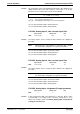
The analog input can be uploaded/downloaded by the drive firmware via a
digital low-pass filter. The limit frequency of this filter is set by this
parameter, if necessary the filter can also be deactivated.
f
grenz
= 1000 / (2 *
π
* T
Eing.
)
f
limit
: limit frequency in Hz
T
input
: time constant of input filter in ms
Fig. 7-47: Calculating the limit frequency of the analog input filter
See also Functional Description "Analog Interface"
See also Functional Description "Analog Inputs"
P-0-0234, Analog input 5, time constant input filter
Input min/max: Default value: Unit:
MPB: 0,250 / 60,000 0,250 ms
The analog input 5 can be read by the drive firmware via a digital low-
pass filter.
Note: Analog input 5 is only available in conjunction with a double-
axis device with configuration of 2 optional cards MA1!
See also Functional Description "Performance Data"
See also Functional Description "Analog Interface"
See also Functional Description "Analog Inputs"
P-0-0235, Analog input 6, time constant input filter
Input min/max: Default value: Unit:
MPB: 0,250 / 60,000 0,250 ms
The analog input 6 can be read by the drive firmware via a digital low-
pass filter.
Note: Analog input 6 is only available in conjunction with a double-
axis device with configuration of 2 optional cards MA1!
See also Functional Description "Performance Data"
See also Functional Description "Analog Interface"
See also Functional Description "Analog Inputs"
P-0-0236, Analog input, assignment B, target parameter
Input min/max: Default value: Unit:
MPB: --- / --- 0 --
In this parameter the IDN of that parameter is entered to which a value
corresponding to the voltage at the respective analog input is to be
written. The scaling is made via P-0-0237, Analog input, assignment A,
scaling per 10V full scale!
v
Function
Function
Function
Function