
Operating instructions


Rexroth IndraDrive Commissioning and Parameterization 7-59
DOK-INDRV*-FU*********-IB01-EN-P
With this parameter it is possible to determine and activate an individual
undervoltage threshold, differing from the standard value, for the DC bus
voltage.
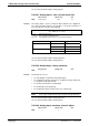
P-0-0115, Device control: status word
Input min/max: Default value: Unit:
MPB: --- / --- --- --
By means of this parameter it is possible to read the drive status (
device control) independent of the master communication that is used.
See also Functional Description "Master Communication"
See also Functional Description "Drive Functions - Drive Halt"
P-0-0116, Device control: control word
Input min/max: Default value: Unit:
MPB: --- / --- --- --
This parameter indicates whether the master communication has
activated the drive.
P-0-0117, Activation of NC reaction on error
Input min/max: Default value: Unit:
MPB: --- / --- 0 --
This parameter allows activating an error reaction controlled by the control
unit. When error reaction controlled by the control unit is active, the
control unit (external control/NC or local MLD) still can input command
values for the drive for 30 s. This allows realizing an error reaction
coordinated by the control unit in the case of error.
Note: When the 30 seconds are over, the error reaction set in
P-0-0119, Best possible deceleration is carried out.
See also Functional Description "NC Reaction on Error"
P-0-0118, Power supply, configuration
Input min/max: Default value: Unit:
MPB: --- / --- 3 --
In parameter P-0-0118 settings with regard to error messages and error
reactions are made for drives that are interconnected via the DC bus and
the module bus ("drive system"). In addition, the handling of DC bus
undervoltage is determined.
Note: The DC bus voltage (power bus) for the "drive system" in
operation is not switched off in the case of non-fatal drive
errors!
See also Functional Description "Power Supply"
Function
Function
Function
Function
Function