
BROADway System Installation Manual


BROADway - Release 4.00 2-29
Installation
Applying Power to the Chassis
Applying Power to the Chassis
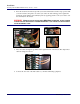
Locate the power switches on the rear of the chassis (O/I) and turn them on (I). After powering up the
BROADway chassis, all the LEDs will go through an initialization process where they all light. After
the cards have initialized, only the top left (MODULE) green LED on each card and one of the NSP101
ACTIVE LEDs will lamp as shown in the following figure. After the standby NSP101 has
synchronized its database with the active NSP101, its ACTIVE LED will link green slowly. These
LEDs remain lit during normal operation.
Slots that have no cards installed will remain unlit.
DANGER! THIS SYSTEM HAS TWO POWER INPUT CONNECTIONS. DISCONNECT BOTH BEFORE
SERVICING TO AVOID ELECTRIC SHOCK. SEE CABLING POWER AND GROUND ON PAGE 2-6.
Should you need to power cycle the BROADway system then power down the chassis using the power
switches at the rear of the chassis (O/I) and wait at least five seconds before powering it back on.
9
INTERFACE
M
O
D
U
L
E
13
A
C
T
I
V
E
A
L
A
R
M
M
O
D
U
L
E
A
C
T
I
V
E
3175
INTERFACE
S
U
M
13
TM
2
1311 15
1
P
W
R
1
E
T
H
2
M
O
D
U
L
E
I
N
T
E
R
F
A
C
E
B
R
O
A
D
w
a
y
NIPTX1 NIPTX2
TX1 TX2 TX3 TX4
NIP RX1 NIP RX2
RX3RX1 RX2 RX4
SCP-2ALARMS
RESET
SCP-1
OSP-1
BSP-3
BSP-2
BSP-1
BSP-4
OSP-2
OSP-3
OSP-4
NIP-5
NSP-1
NSP-2
NIP-6
NIP-7
NIP-8
NIP-1
NIP-2
NIP-3
NIP-4
UIP-2
UIP-1