
BROADway System Installation Manual


2-22 BROADway - Release 4.00
Installation
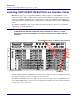
Installing the BSP200 Line Interface Card
Cabling the BSP200
The BSP200 line interface cards use the 75Ohm BNC ports TX1/RX1, TX2/RX2, TX3/RX3, and TX4/
RX4 respectively on the top I/O panel of the BROADway chassis.
To make your DS3 cable connections:
1. Connect the DS3 inputs by connecting 75Ohm BNC coaxial cables to TX1/RX1 through TX4/
RX4.
2. Connect the other end of these cables to your DS3 terminating equipment.
BSP200 LED Indicators
Each BSP200 line card has two LED indicators that describe the operational status of the module itself.
There are a further two LED indicators per card that describe the status of the line interface.
The following tables describe the status of the BSP200 line interface card based upon the front panel
LED status of the card.
MODULE Red LED
(Top)
MODULE Green LED
(Bottom)
Status
Off Off No power to the card
Off On Card operating normally
On Off Card failure
On On Card initializing during system
power up
CKIN-1
NIP TX1 NIP TX2
TX2TX1 TX3 TX4
NIP RX1 NIP RX2
RX3RX1 RX2 RX4
ALARMS
ACO
SCP-2
ETH-1CKIN-2 ETH-2
SCP-1
Connect BNC coaxial cables
9
INTERFACE
M
O
D
U
L
E
13
A
C
T
I
V
E
A
L
A
R
M
M
O
D
U
L
E
A
C
T
I
V
E
3175
INTERFACE
S
U
M
13
TM
2
1311 15
1
P
W
R
1
E
T
H
2
M
O
D
U
L
E
I
N
T
E
R
F
A
C
E
A
D
w
a
y
OSP-1
BSP-3
BSP-2
BSP-1
BSP-4
NIP-5
NSP-1
NSP-2
NIP-1
UIP-2
UIP-1