
BROADway System Installation Manual


2-20 BROADway - Release 4.00
Installation
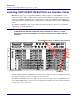
Installing the NHP160 Line Interface Card
4. Connect the other end of the cables to your terminating equipment.
For cable pinouts of the NHP160 SCSI port connector, see NHP160 Connector Pinouts on page A-8.
NHP160 LED Indicators
Each NHP160 line card in a UIP slot has two LED indicators that describe the operational status of the
module itself. There is a further single LED indicator per physical interface that describes the status of
the line interface. The active LED position is not used on the NHP160.
The following tables describe the status of the NHP160 line interface card based upon the front panel
LED status of the card.
If the card failure sequence is displayed, remove the card and re-insert it into the chassis. If the card
failure sequence is still displayed, then replace the card.
Line status (per port):
MODULE Red LED
(Top)
MODULE Green LED
(Bottom)
Status
Off Off No power to the card
Off On Card operating normally
On Off Card failure
On On Card initializing during system
power up
Port LED Port State
off The card is not configured, or alarm reporting is disabled on the
interface
green Interface operating normally
blinking green Interface performing a diagnostic test
blinking red Yellow alarm (RAI)
red Interface failure (LOS, OOF, AIS)
9
A
C
T
I
V
E
A
L
A
R
M
M
O
D
U
L
E
A
C
T
I
V
E
3175
S
U
M
TM
2
1311 15
1
P
W
R
1
E
T
H
M
O
D
U
L
E
I
N
T
E
R
F
A
C
E
D
w
a
y
BSP-3
BSP-2
BSP-1
BSP 4
NSP-1
NSP 2
UIP-2
UIP-1