
BROADway System Installation Manual


2-18 BROADway - Release 4.00
Installation
Installing the NIP400 Line Interface Card
NIP400 LED Indicators
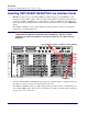
Each NIP400 line card has two LED indicators that describe the operational status of the module itself.
There is a further single LED indicator per physical interface that describes the status of the modules
four line interfaces.
The following tables describe the LED status of the NIP400 line interface card.
If the card failure sequence is displayed, remove the card and re-insert it into the chassis. If the card
failure sequence is still displayed, then replace the card.
Line status (per port):
MODULE Red LED
(Top)
MODULE Green LED
(Bottom)
Status
Off Off No power to the card
Off On Card operating normally
On Off Card failure
On On Card initializing during system
power up
Port LED Port State
off The card is not configured, or alarm reporting is disabled on the
interface
green Interface operating normally
blinking green Interface performing a diagnostic test
blinking red Yellow alarm (RAI)
red Interface failure (LOS, OOF, AIS)
INTERFACE
O
D
U
L
E
13
INTERFACE
13
B
R
O
A
OSP-1
OSP-2
OSP-3
OSP-4
NIP-5
NIP-6
NIP-7
NIP-8
NIP-1
NIP-2
NIP-3
NIP-4
NIP TX1 NIP TX2
TX2TX1
TX3
TX4
ALARMS
ACO
SCP-2