
BROADway System Installation Manual


2-14 BROADway - Release 4.00
Installation
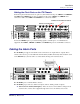
Installing the NSP101 Control Card
To install the NSP101, open the ejector tabs and slide the card into its proper slot until you feel
resistance, then push to close the ejector tabs into their locking position against the metal rails. Verify
that the card is firmly placed by applying pressure to the ejector tabs to seat the card fully in the chassis.
WARNING! WHEN INSTALLING OR REPLACING BROADWAY HARDWARE, ALWAYS ADHERE
TO GOOD PRACTICE WITH RESPECT TO ESD PROCEDURES—USE A REGULARLY AND PROPERLY
TESTED GROUNDING STRAP.
Each NSP101 has eight front panel LED indicators. From left to right, the two rows of indicators on
each NSP101 indicate NSP101 module operating status (common indicators to all control and line
interface cards), active card, power input status and Ethernet line activity.
The following tables describe the status of the NSP101 control card based upon the front panel LED
status of the card.
Active or standby NSP101:
CAUTION! WHEN BROADWAY DATABASES ARE SYNCHRONIZING BETWEEN THE ACTIVE
AND STANDBY BROADWAY SYSTEMS, THE ACTIVE LEDS ON THE NSP101S BLINK RAPIDLY
TO SIGNIFY A FILE TRANSFER IS IN PROGRESS. YOU MUST WAIT UNTIL THESE LEDS HAVE
STOPPED FLASHING BEFORE YOU PERFORM ANY OPERATION TO RE-INITIALIZE THE BROADWAY
SYSTEM EITHER THROUGH A REBOOT OR FORCED NSP101 PROTECTION SWITCHOVER.
MODULE Red LED
(Top)
MODULE Green LED
(Bottom)
Status
Off Off No power to the card
Off On Card operating normally
On Off Card failure
On On Card initializing during system
power up
ACTIVE Green LED Status
On This is the Active NSP101
Blinking Slow This is the Standby NSP101
Blinking Fast The NSP101s are synchronizing databases
9
INTERFACE
M
O
D
U
L
E
13
A
C
T
I
V
E
A
L
A
R
M
U
L
E
A
C
T
I
V
E
3175
INTERFACE
S
U
M
13
TM
2
1311 15
1
P
W
R
1
E
T
H
2
U
L
E
A
C
E
A
D
w
a
y
OSP-1
BSP-3
BSP-2
BSP-1
BSP-4
NIP-5
NSP-1
NSP-2
NIP-1
UIP-2
UIP-1