Access Navigator USER MANUAL Part Number: 770-0079-AP Product Release: 1.
Copyright© 2003 Carrier Access Corporation. All rights reserved. The information presented in this manual is subject to change without notice and does not represent a commitment on the part of Carrier Access Corporation. The hardware and software described herein are furnished under license(s) or non-disclosure agreement(s). The hardware, software, and manual may be used or copied only in accordance with the terms of such agreement(s), including, but not limited to, the software license contained herein.
PREFACE Preface In this Preface n Compliance ... iv n Notices ... iv n Electrostatic Discharge (ESD) Precautions ... v n Carrier Access Software License Agreement ... vi n Warranty ...
Preface Compliance USA l UL 1950, 3rd Edition l FCC Part 15, Class A l FCC Part 68 l NEBS Level 3 for Type 2 and 4 equipment GR-1089-CORE GR-63-CORE CANADA l CSA C22.2 No. 950.95 l ICES-003, Class A l CS-03 See Chapters 2, 3, and 4 for detailed compliance requirements on each product. Notices This manual contains important information and warnings that must be followed to ensure safe operation of the equipment.
Preface Electrostatic Discharge (ESD) Precautions ESD can damage processors, circuit boards, and other electronic components. Always observe the following precautions before installing a system component. 1. Do not remove a component from its protective packaging until ready to install it. 2. Wear a wrist grounding strap and attach it to a metal part of the system unit before handling components.
Preface Carrier Access Software License Agreement PLEASE CAREFULLY READ THE FOLLOWING TERMS AND CONDITIONS CONTAINED IN THIS LICENSE (THE "LICENSE") BEFORE OPENING THE SOFTWARE PACKAGE; OPENING THIS PACKAGE INDICATES THAT YOU HAVE ACCEPTED THESE TERMS AND CONDITIONS AND AGREE TO BE BOUND BY THEM. CARRIER ACCESS CORPORATION provides this Software and licenses its use to you, the LICENSEE, pursuant to the following terms.
Preface LICENSEE agrees that it will not export or re-export the Software in any form without the appropriate United States and foreign government licenses. LICENSEE agrees that its obligations pursuant to this Section shall survive and continue after any termination or expiration of rights under this License. Copyright The Software is copyrighted by LICENSOR and, except as permitted by this License, LICENSEE may not duplicate the Software or disclose it to any other party.
Preface (INCLUDING NEGLIGENCE, CONTRACT AND TORT), EVEN IF LICENSOR HAS BEEN ADVISED OF THE POSSIBILITY OF SUCH DAMAGES.
Preface Warranty Carrier Access Corporation conditionally warrants to BUYER that PRODUCTS are free from substantial defect in material and workmanship under normal use given proper installation and maintenance for the period of five years from the date of shipment by Carrier Access Corporation. BUYER will promptly notify Carrier Access Corporation of any defect in the PRODUCT.
Preface Warranty Product Returns Before returning any equipment to Carrier Access, first contact the distributor or dealer from which you purchased the product. A Return Material Authorization (RMA) number is required for all equipment returned to Carrier Access. Call Carrier Access Customer Support at (800) 786-9929 or (303) 442-5455 for RMA number, repair/warranty information and shipping instructions.
TABLE OF CONTENTS TABLE OF CONTENTS Preface Compliance . . . . . . . . . . . . . . . . . . . . . . . . . . . . . . . . . . . . . . . . . . . . . . . . . iv Notices . . . . . . . . . . . . . . . . . . . . . . . . . . . . . . . . . . . . . . . . . . . . . . . . . . . . iv Electrostatic Discharge (ESD) Precautions . . . . . . . . . . . . . . . . . . . . . . . . . .v Carrier Access Software License Agreement . . . . . . . . . . . . . . . . . . . . . . . vi License . . . . . . . . . . . . . . . . . . . . . . .
Table of Contents Configuration . . . . . . . . . . . . . . . . . . . . . . . . . . . . . . . . . . . . . . . . . . . . . . 2-6 Applications . . . . . . . . . . . . . . . . . . . . . . . . . . . . . . . . . . . . . . . . . . . . . . . 2-7 Interfaces . . . . . . . . . . . . . . . . . . . . . . . . . . . . . . . . . . . . . . . . . . . . . . . . . . 2-7 Specifications . . . . . . . . . . . . . . . . . . . . . . . . . . . . . . . . . . . . . . . . . . . . . . 2-7 DCS Operation . . . . . . . . . . . . . . . .
Table of Contents Environmental. . . . . . . . . . . . . . . . . . . . . . . . . . . . . . . . . . . . . . . . . . 3-13 Physical . . . . . . . . . . . . . . . . . . . . . . . . . . . . . . . . . . . . . . . . . . . . . . . 3-13 Compliance Requirements . . . . . . . . . . . . . . . . . . . . . . . . . . . . . . . . . . . . 3-14 FCC Requirements . . . . . . . . . . . . . . . . . . . . . . . . . . . . . . . . . . . . . . 3-14 Telcordia (Bellcore) Requirements. . . . . . . . . . . . . . . . . . . . . . . . . .
Table of Contents 5 Physical Installation Compliance and Safety Requirements . . . . . . . . . . . . . . . . . . . . . . . . . . . 5-2 Tools and Materials. . . . . . . . . . . . . . . . . . . . . . . . . . . . . . . . . . . . . . . . . . 5-3 Unpacking and Inspection. . . . . . . . . . . . . . . . . . . . . . . . . . . . . . . . . . . . . 5-3 Horizontal 19-Inch Rack Mount . . . . . . . . . . . . . . . . . . . . . . . . . . . . . . . . 5-4 Installation Summary . . . . . . . . . . . . . . . . . . . . . . . .
Table of Contents DSX-1 Cable Connections . . . . . . . . . . . . . . . . . . . . . . . . . . . . . . . . . . . . . 6-8 Installation Summary . . . . . . . . . . . . . . . . . . . . . . . . . . . . . . . . . . . . . 6-8 Precautions . . . . . . . . . . . . . . . . . . . . . . . . . . . . . . . . . . . . . . . . . . . . . 6-8 Tools and Materials . . . . . . . . . . . . . . . . . . . . . . . . . . . . . . . . . . . . . . 6-9 Prepare DSX-1 Cables . . . . . . . . . . . . . . . . . . . . . . . . . . . . . . . . .
Table of Contents Dress Cables and Wires. . . . . . . . . . . . . . . . . . . . . . . . . . . . . . . . . . . . . . Installation Summary . . . . . . . . . . . . . . . . . . . . . . . . . . . . . . . . . . . . Tools and Materials . . . . . . . . . . . . . . . . . . . . . . . . . . . . . . . . . . . . . Dress Cables and Wires . . . . . . . . . . . . . . . . . . . . . . . . . . . . . . . . . . Acceptance Test . . . . . . . . . . . . . . . . . . . . . . . . . . . . . . . . . . . . . . . . . . .
Table of Contents 7 Start Management Session Management Requirements . . . . . . . . . . . . . . . . . . . . . . . . . . . . . . . . . . . . 7-2 Command Line Interface Conventions . . . . . . . . . . . . . . . . . . . . . . . . . . . 7-3 RS-232 Management . . . . . . . . . . . . . . . . . . . . . . . . . . . . . . . . . . . . . . . . . 7-4 RS-232 Management Requirements . . . . . . . . . . . . . . . . . . . . . . . . . . 7-4 Procedure Summary . . . . . . . . . . . . . . . . . . . . . . . . . . . . . . . .
Table of Contents Test Groom DS1 Circuits . . . . . . . . . . . . . . . . . . . . . . . . . . . . . . . . . . . . Provision “Drop” DS1 Circuits to Subscribers . . . . . . . . . . . . . . . . . . . . Provision and Connect ISDN PRI Channels . . . . . . . . . . . . . . . . . . . . . . Provision and Connect ISDN BRI 3DS0 Channels . . . . . . . . . . . . . . . . Provision and Connect DS0s. . . . . . . . . . . . . . . . . . . . . . . . . . . . . . . . . . Turn Up Service . . . . . . . . . . . . . . . . . . . . .
Table of Contents Provision Drop DS1 to Remote Access Bank II . . . . . . . . . . . . . . . . . . 11-15 Test DS1 Circuits . . . . . . . . . . . . . . . . . . . . . . . . . . . . . . . . . . . . . . . . . . 11-17 Provision DS0s. . . . . . . . . . . . . . . . . . . . . . . . . . . . . . . . . . . . . . . . . . . . 11-17 Provision DS0 Crossconnects . . . . . . . . . . . . . . . . . . . . . . . . . . . . . . . . 11-19 Create Fractional Interfaces (if required). . . . . . . . . . . . . . . . . . . . . . . .
Table of Contents 14 Alarm Clearing Identify Alarm Clearing Procedure . . . . . . . . . . . . . . . . . . . . . . . . . . . . . 14-2 Clear Alarms – FDL . . . . . . . . . . . . . . . . . . . . . . . . . . . . . . . . . . . . . . . . 14-3 Clear Alarms – EOC . . . . . . . . . . . . . . . . . . . . . . . . . . . . . . . . . . . . . . . . 14-8 Clear Alarms – SNMP. . . . . . . . . . . . . . . . . . . . . . . . . . . . . . . . . . . . . . 14-14 Clear Alarms – Status Indicators. . . . . . . . . . . . . . . . . .
Table of Contents GR-303 Status and Performance . . . . . . . . . . . . . . . . . . . . . . . . . . . . . . 15-22 Status CRV . . . . . . . . . . . . . . . . . . . . . . . . . . . . . . . . . . . . . . . . . . . 15-22 Status ISDN CRV . . . . . . . . . . . . . . . . . . . . . . . . . . . . . . . . . . . . . . 15-23 Status EOC . . . . . . . . . . . . . . . . . . . . . . . . . . . . . . . . . . . . . . . . . . . 15-25 Status TMC . . . . . . . . . . . . . . . . . . . . . . . . . . . . . . . . . . . . . . . . .
Table of Contents 16 Maintenance Procedures Compliance and Safety Requirements . . . . . . . . . . . . . . . . . . . . . . . . . . 16-2 Repair and Return Procedure . . . . . . . . . . . . . . . . . . . . . . . . . . . . . . . . . 16-2 Replace Controller Card . . . . . . . . . . . . . . . . . . . . . . . . . . . . . . . . . . . . . 16-3 Procedure Summary . . . . . . . . . . . . . . . . . . . . . . . . . . . . . . . . . . . . . 16-3 Overview . . . . . . . . . . . . . . . . . . . . . . . . . . . . . . . . .
Table of Contents 18 CLI Language Reference Overview . . . . . . . . . . . . . . . . . . . . . . . . . . . . . . . . . . . . . . . . . . . . . . . . . 18-2 CLI Requirements . . . . . . . . . . . . . . . . . . . . . . . . . . . . . . . . . . . . . . . . . . 18-3 CLI over RS-232. . . . . . . . . . . . . . . . . . . . . . . . . . . . . . . . . . . . . . . . 18-3 CLI over Telnet. . . . . . . . . . . . . . . . . . . . . . . . . . . . . . . . . . . . . . . . . 18-4 Using CLI Command Scripts . . . . . . . . . .
Table of Contents Connect . . . . . . . . . . . . . . . . . . . . . . . . . . . . . . . . . . . . . . . . . . . . . Connect Remote Interface . . . . . . . . . . . . . . . . . . . . . . . . . . . . . . . Delete Interface . . . . . . . . . . . . . . . . . . . . . . . . . . . . . . . . . . . . . . . Delete User . . . . . . . . . . . . . . . . . . . . . . . . . . . . . . . . . . . . . . . . . . Disconnect . . . . . . . . . . . . . . . . . . . . . . . . . . . . . . . . . . . . . . . . . . . Disconnect Remote .
Table of Contents Send Remote SDSL Payload Loopup . . . . . . . . . . . . . . . . . . . . . . 18-84 Send Remote T1 Payload Loopup . . . . . . . . . . . . . . . . . . . . . . . . . 18-85 Send Remote T1 TSI Loopup . . . . . . . . . . . . . . . . . . . . . . . . . . . . 18-86 Send Remote T1Drop Line Loopup . . . . . . . . . . . . . . . . . . . . . . . . 18-87 Send Remote T1Drop Payload Loopup . . . . . . . . . . . . . . . . . . . . . 18-88 Send Remote T1Drop TSI Loopup . . . . . . . . . . . . . . . . . . . .
Table of Contents Set Remote T1Drop Framing . . . . . . . . . . . . . . . . . . . . . . . . . . . Set Remote T1Drop LBO . . . . . . . . . . . . . . . . . . . . . . . . . . . . . . Set Remote T1Drop Linecode . . . . . . . . . . . . . . . . . . . . . . . . . . . Set Remote T1Drop PRM . . . . . . . . . . . . . . . . . . . . . . . . . . . . . . Set Remote V35 ClockInv . . . . . . . . . . . . . . . . . . . . . . . . . . . . . Set Remote V35 CTS . . . . . . . . . . . . . . . . . . . . . . . . . . . . . . . . .
Table of Contents Show Users . . . . . . . . . . . . . . . . . . . . . . . . . . . . . . . . . . . . . . . . . 18-154 Status Clock . . . . . . . . . . . . . . . . . . . . . . . . . . . . . . . . . . . . . . . . . 18-155 Status CRV . . . . . . . . . . . . . . . . . . . . . . . . . . . . . . . . . . . . . . . . . 18-156 Status DS0 . . . . . . . . . . . . . . . . . . . . . . . . . . . . . . . . . . . . . . . . . . 18-157 Status DS1 . . . . . . . . . . . . . . . . . . . . . . . . . . . . . . . . . . . . . . .
Table of Contents B FDL Interface Overview . . . . . . . . . . . . . . . . . . . . . . . . . . . . . . . . . . . . . . . . . . . . . . . . . . B-2 Remote Provisioning Requirements . . . . . . . . . . . . . . . . . . . . . . . . . . . . . B-3 Access Navigator Remote Provisioning Requirements . . . . . . . . . . . B-3 Access Bank II Remote Provisioning Requirements . . . . . . . . . . . . . B-3 Adit 600 TDM Remote Provisioning Requirements . . . . . . . . . . . . . B-3 Remote Provisioning Capabilities. . .
CHAPTER Introduction In this Chapter n Overview ... 1-2 n Features and Benefits ... 1-3 n Access Navigator Configurations ... 1-3 n System Architecture ... 1-4 n Carrier Access Support Products ... 1-5 n Management ...
Introduction Overview Overview The Access Navigator® Multiservice Digital Access (MDA) system combines the functionality of a miniature 1/0 digital crossconnect switch (DCS) with the call processing and concentration capabilities of a GR-303 digital loop carrier (DLC) system. Providing up to 32 DS1 ports (768 DS0s) in one small package, the Access Navigator fits easily into small collocation spaces and phone closets.
Introduction Features and Benefits Features and Benefits The Access Navigator provides the ability to concentrate and groom a mix of voice and data information. The 1/0 crossconnect functionality of the DCS allows data channels from a variety of locations to be crossconnected and packed into dedicated T1s. The time slot interchange (TSI) functionality of the GR-303 system dynamically assigns voice traffic to the local digital switch.
Introduction System Architecture System Architecture The Access Navigator is a distributed system in which the Access Navigator is the host terminal located at a co-location or customer premise. CA’s Access Bank® and Adit® 600 products operate as remotely managed service units at the customer premises.
Introduction Carrier Access Support Products Carrier Access Support Products Access Banks Access Bank® family of T1 CSU products (see Figure 1-2) includes: l Access Bank I – up to 24 voice channels l Access Bank II – up to 24 voice channels plus T1 and V.35 data interfaces l Access Bank II / SNMP – up to 24 voice channels plus T1 and V.35 data, and Ethernet SNMP l Access Bank II / SDSL – up to 24 voice channels plus SDSL and V.
Introduction Management Management The Access Navigator includes RS-232 and Ethernet ports for local and remote management, provisioning, and testing (see Figure 1-3). Flow-through provisioning enables the Access Navigator to pre-provision, test and manage remote Access Bank II units to provide the required voice and data services. The Access Navigator also provides host support for provisioning and managing Adit 600 terminals.
Introduction SNMP SNMP The Access Navigator SNMP Agent is based on the SNMPv1 standard.
Introduction Valet and NetworkValet EMS Software Valet and NetworkValet EMS Software Valet™ and NetworkValet™ EMS are enhanced element management systems with simple graphical user interfaces. Valet is ideal for technicians deploying Access Navigators in carrier networks, while the full-featured NetworkValet EMS with alarms and performance monitoring is intended for Network Operations Centers (NOCs).
CHAPTER Access Navigator / DCS Service Manager In this Chapter n Overview ... 2-2 n System Architecture ... 2-3 n Features and Benefits ... 2-4 n Configuration ... 2-6 n Applications ... 2-7 n Interfaces ... 2-7 n Specifications ... 2-7 n Compliance Requirements ... 2-10 n Ordering Information ...
Access Navigator / DCS Service Manager Overview Overview The Access Navigator® / DCS Service Manager is a complete service solution for managing 4 to 32 T1 access connections. The power of a remotely managed, 32-port, Digital Crossconnect System (DCS) is contained in only 1½ rack units. Integrated testing and optional common equipment redundancy ensure carrier-class service availability.
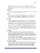
Access Navigator / DCS Service Manager System Architecture System Architecture Remote Management 24 PBX Lines ACCE SS BAN K I Stations Self Test Normal Norm al Netw ork Loopback Normal Rem ote Normal Key System Alarm Cut-O ff Test Statu s Voice Switch T1 Framing Voice Fax Input Monit or Outp ut Moni tor T1 -4 8Vdc Return Ethernet Voice Telnet & SNMP Ground RS-232 Drop DS1s Tip & Ring Modem Access Bank I Voice and Data Public Network Groom T1s Voice Lines ACCES S BAN K II T1 S pan 1
Access Navigator / DCS Service Manager Features and Benefits Features and Benefits Functions The Access Navigator / DCS Service Manager is a transport element that combines the functions of a 32-port T1 digital crossconnect system, T1 channel/data service unit (CSU), T1 diagnostic test equipment, and Access Bank® II host controller into a modular chassis 1½ rack units high (see Figure 2-2).
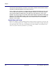
Access Navigator / DCS Service Manager Management Network Operations Center On-Net Location Customer Wiring Closet Customer Premises Voice Lines ACCESS BANK II T1 Span 1 PBX Stations T1 Span 2 T1 Test 1 CLI/Telnet SNMP Access Navigator Element Manager TCP/IP Network Key System Fax T1 Test 2 V. 35 DCE V. 35 St atus Access Navigator FDL RS 232 Data V.
Access Navigator / DCS Service Manager Configuration Configuration l Hardware configuration: Modular construction with plug-in cards includes built-in circuit and network testing and fuse-less protection (see Figure 2-4). l Software configuration: Operating system is stored in upgradeable flash memory. Configuration and provisioning data are stored in nonvolatile RAM, protected from power interruptions.
Access Navigator / DCS Service Manager Applications Applications l T1 Service POP-In-A-Box: Customer-located T1 access management for carriers l End-Office T1 Grooming: T1 access consolidation, provisioning, protection, and service management l DCS Host Control of Access Bank II: Flow-through remote management and bandwidth grooming of Access Bank IIs l PCS and Cellular Site T1 Bandwidth Management: Drop, groom, and test multiple T1 connections between cell sites and hubs Interfaces l DS1 Interface: Two
Access Navigator / DCS Service Manager System Clocking l ANSI T1.
Access Navigator / DCS Service Manager Compliance Compliance USA l UL 1950, 3rd Edition l FCC Part 15, Class A l FCC Part 68 l NEBS Level 3 for Type 2 and 4 equipment GR-1089-CORE GR-63-CORE CANADA l CSA C22.2 No. 950.95 l ICES-003, Class A l CS-03 Power l Input power: –42 to –60 VDC @ 1.5A l Dual feed DC power input terminals l Power dissipation: 65 watts (225 Btu/hr.
Access Navigator / DCS Service Manager Compliance Requirements Compliance Requirements FCC Requirements This equipment complies with Part 15 and Part 68 of the Federal Communications Commission (FCC) Rules. Part 15, Class A This equipment has been tested and found to comply with the limits for a Class A digital device in accordance with Part 15 of the FCC Rules. These limits provide reasonable protection against harmful interference when equipment is operated in a commercial environment.
Access Navigator / DCS Service Manager Telcordia (Bellcore) Requirements provide advance notice in order for you to make necessary modifications to maintain uninterrupted service. If you need to make repairs or modifications to the equipment, please first contact Carrier Access Corporation for repair, modification, and warranty information. Customer repairs and modifications are limited to the replacement of circuit boards; any other repairs or modifications will void your warranty.
Access Navigator / DCS Service Manager CSA Requirements CSA Requirements This telecommunication network equipment conforms with Canadian Standards Association (CSA) standard C22.2 No. 950.95. To maintain this compliance, all access covers must be replaced after servicing the equipment to prevent fires from spreading to nearby equipment.
CHAPTER Access Navigator / GR-303 + Data Host In this Chapter n Overview ... 3-2 n System Architecture ... 3-3 n Features and Benefits ... 3-4 n GR-303 Services ... 3-4 n DCS Services ... 3-6 n Management Architecture ... 3-7 n Configuration ... 3-9 n Applications ... 3-10 n Interfaces ... 3-10 n Specifications ... 3-11 n Compliance Requirements ... 3-14 n Ordering Information ...
Access Navigator / GR-303 + Data Host Overview Overview The Access Navigator® / GR-303 + Data Host offers a highly integrated solution for combining multi-line local voice and data services on customer T1 access lines. Using the Telcordia® standard GR-303 switching protocol, up to 672 customer telephone channels can be assigned on a call-by-call basis to Class 5 local digital switch T1 connections.
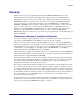
Access Navigator / GR-303 + Data Host System Architecture System Architecture Remote Management 24 PBX Lines A CCESS BANK I Stations Self Test Normal N ormal Network L oopback Normal Remote Normal Key System A larm C ut-Off Test Status T1 Fr aming Voice GR-303 Voice Switch with GR-303 DCS Voice and Data Internet, Data, Private and Special Services Ethernet RS-232 Switch DS1s Drop DS1s Fax In put M onitor O utput M onitor T1 -48Vd c Return Groun d Tip & Rin g Modem Access Bank I Voice a
Access Navigator / GR-303 + Data Host Features and Benefits Features and Benefits The Access Navigator / GR-303 + Data Host is a transport element that combines the functions of a GR-303 digital terminal, 32-port T1 digital crossconnect system, T1 channel/data service unit (CSU), T1 diagnostic test equipment, and Access Bank® II host controller into a modular chassis 1½ rack units high.
Access Navigator / GR-303 + Data Host GR-303 Services CA's Access Navigator / GR-303 + Data Host, together with the Access Bank II and Adit 600, bring costeffective concentration and remote management to competitive local carriers with a new level of serviceability and space efficiency.
Access Navigator / GR-303 + Data Host DCS Services DCS Services The Access Navigator provides all the grooming and filling functions of a 1/0 digital crossconnect system (DCS) to maximize T1 usage. With carrier/customer demarcation testing, carriers are able to decrease maintenance costs and labor, while increasing service availability.
Access Navigator / GR-303 + Data Host Management Architecture Management Architecture Access Navigators provide management access via Ethernet SNMP, Telnet CLI, and RS-232 CLI. Valet™ and NetworkValet™ EMS software provides a graphical user interface (GUI) for SNMP management. Flow-through provisioning of the remote Access Bank II and testing control over T1 connections reduce truck rolls and monitors voice and data service availability at customer locations.
Access Navigator / GR-303 + Data Host FDL Management FDL Management When T1 Type I lines are available, the Access Navigator can use the ESF Faciltiy Data Link channel to manage remote Access Bank II and Adit 600 terminals. Network Operations Center On-Net Location Customer Wiring Closet Customer Premises Voice Lines ACCESS BANK II T1 Span 1 PBX Stations T1 Span 2 T1 Test 1 CLI/Telnet SNMP Access Navigator Element Manager TCP/IP Network Key System Fax T1 Test 2 V. 35 DCE V.
Access Navigator / GR-303 + Data Host Configuration Configuration The Access Navigator / GR-303 + Data Host combines call processing and concentration capabilities of a GR-303 digital loop carrier (DLC) system with the functionality of a miniature 1/0 digital crossconnect switch (DCS). Providing up to 32 DS1 ports (768 DS0s) in one small package, the Access Navigator fits easily into small collocation spaces and phone closets.
Access Navigator / GR-303 + Data Host Applications Applications l T1 Service POP-In-A-Box: Customer-located T1 access management for carriers l Call Concentration: Variable concentration of voice calls for more efficient use of backhaul T1s and switch resources l End-Office T1 Grooming: T1 access consolidation, provisioning, protection, and service management l Host Control of Access Bank II: Flow-through remote management and bandwidth grooming of Access Bank IIs Interfaces l DS1 Interface: Two Champ® 6
Access Navigator / GR-303 + Data Host Specifications Specifications GR-303 Operation l l l l l l l l l l Up to 32 T1s per system Primary and redundant protection for EOC and TMC GR-303 to TR-08 translation for CA’s Access Bank I/TR-08 GR-303 Direct Inward Dial (DID) support for Lucent 5ESS switches GR-303 line concentration of 4:1 TDM ISDN BRI services Alarm and maintenance support for DS1 terminations Compatible with Lucent, Nortel, and Siemens switches Configurable concentration ratios Programmable call
Access Navigator / GR-303 + Data Host GR-303 Signaling GR-303 Signaling l GR-303 ABCD robbed-bit signal codes l GR-303 Direct Inward Dial (DID) signaling for Lucent switches l GR-303 4:1 TDM mode support for ISDN BRI l FXS loop start and ground start DCS Signaling l Robbed-bit and clear channel connections at DS0 level l FXS/FXO loop start and ground start l E&M robbed bit signaling Management Interfaces l l l l l Command line interface (CLI) for provisioning and maintenance RS-232 interface for local
Access Navigator / GR-303 + Data Host Compliance Compliance USA l UL 1950, 3rd Edition l FCC Part 15, Class A l FCC Part 68 l NEBS Level 3 for Type 2 and 4 equipment GR-1089-CORE GR-63-CORE CANADA l CSA C22.2 No. 950.95 l ICES-003, Class A l CS-03 Power l Input power: –42 to –60 VDC @ 1.5A l Dual feed DC power input terminals l Power dissipation: 65 watts (225 Btu/hr.
Access Navigator / GR-303 + Data Host Compliance Requirements Compliance Requirements FCC Requirements This equipment complies with Part 15 and Part 68 of the Federal Communications Commission (FCC) Rules. Part 15, Class A This equipment has been tested and found to comply with the limits for a Class A digital device in accordance with Part 15 of the FCC Rules. These limits provide reasonable protection against harmful interference when equipment is operated in a commercial environment.
Access Navigator / GR-303 + Data Host Telcordia (Bellcore) Requirements provide advance notice in order for you to make necessary modifications to maintain uninterrupted service. If you need to make repairs or modifications to the equipment, please first contact Carrier Access Corporation for repair, modification, and warranty information. Customer repairs and modifications are limited to the replacement of circuit boards; any other repairs or modifications will void your warranty.
Access Navigator / GR-303 + Data Host CSA Requirements CSA Requirements This telecommunication network equipment conforms with Canadian Standards Association (CSA) standard C22.2 No. 950.95. To maintain this compliance, all access covers must be replaced after servicing the equipment to prevent fires from spreading to nearby equipment.
CHAPTER Access Navigator / GR-303 Host with P-Phone In this Chapter n Overview ... 4-2 n System Architecture ... 4-3 n Features and Benefits ... 4-4 n GR-303 Services ... 4-4 n P-Phone Services ... 4-6 n DCS Services ... 4-7 n Management Architecture ... 4-8 n Configuration ... 4-10 n Applications ... 4-11 n Interfaces ... 4-11 n Specifications ... 4-12 n Compliance Requirements ... 4-15 n Ordering Information ...
Access Navigator / GR-303 Host with P-Phone Overview Overview The Access Navigator® / GR-303 Host with P-Phone offers a highly integrated solution for combining multi-line local voice and data services on customer T1 access lines. Using the Telcordia® standard GR-303 switching protocol, up to 672 customer telephone channels can be assigned on a call-by-call basis to Class 5 local digital switch T1 connections.
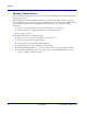
Access Navigator / GR-303 Host with P-Phone System Architecture System Architecture Remote Management 24 PBX Lines ACCESS BANK I Stations Self Test Normal Normal Network Loopba ck Normal Remot e Normal Voice Switch (GR-303) Key System Alarm Cut-Of f Test Status T1 Framing Voice Ethernet RS-232 Switch DS1s Drop DS1s Fax Input Monitor Output Monito r T1 -48V dc Retu rn Grou nd Tip & R ing Modem Voice Voice and Data Public Network DCS Voice and Data Internet, Data, Private and Special
Access Navigator / GR-303 Host with P-Phone Features and Benefits Features and Benefits The Access Navigator / GR-303 with P-Phone is a transport element that combines the functions of a GR-303 digital terminal, 32-port T1 digital crossconnect system, T1 channel/data service unit (CSU), T1 diagnostic test equipment, and Access Bank® II host controller into a modular chassis 1½ rack units high.
Access Navigator / GR-303 Host with P-Phone GR-303 Services Remote Management 24 PBX Lines ACCE SS BANK I Stations Self Test Norm al Normal Network Loop back Norm al Remote Norm al Key System Alarm Cut-O ff Tes t Status T1 Frami ng Voice Fax Input Moni tor Output Monitor T1 -48Vdc Return Gr ound Tip & Ring Ethernet Telnet & SNMP GR-303 Voice & ISDN BRI Switch Data DS1s Modem RS-232 Drop DS1s Access Bank I Voice and Data Voice Lines ACCE SS BANK II T1 S pan 1 PBX T1 Test 1 Key Syste
Access Navigator / GR-303 Host with P-Phone P-Phone Services P-Phone Services The Access Navigator / GR-303 Host with P-Phone includes Nortel Proprietary Phone (P-Phone) Centrex service support using remote Adit 600 terminals with P-Phone service cards. The cards convert the customer’s analog P-Phone signals to more efficient digital loop carriers. These digital signals that are then transmitted over DS0s on the Access Navigator’s drop DS1.
Access Navigator / GR-303 Host with P-Phone DCS Services DCS Services The Access Navigator provides all the grooming and filling functions of a 1/0 digital crossconnect system (DCS) to maximize T1 usage. With carrier/customer demarcation testing, carriers are able to decrease maintenance costs and labor, while increasing service availability.
Access Navigator / GR-303 Host with P-Phone Management Architecture Management Architecture Access Navigators provide management access via Ethernet SNMP, Telnet CLI, and RS-232 CLI. Valet™ and NetworkValet™ EMS software provides a graphical user interface (GUI) for SNMP management. Flow-through provisioning of the remote Access Bank II and testing control over T1 connections reduce truck rolls and monitors voice and data service availability at customer locations.
Access Navigator / GR-303 Host with P-Phone FDL Management FDL Management When T1 Type I lines are available, the Access Navigator can use the ESF Faciltiy Data Link to manage remote Access Bank II and Adit 600 terminals. (FDL can not be used to manage remote Adit 600s with P-Phone cards.
Access Navigator / GR-303 Host with P-Phone Configuration Configuration The Access Navigator / GR-303 Host with P-Phone combines call processing and concentration capabilities of a GR-303 digital loop carrier (DLC) system with the functionality of a miniature 1/0 digital crossconnect switch (DCS). Providing up to 32 DS1 ports (768 DS0s) in one small package, the Access Navigator fits easily into small collocation spaces and phone closets.
Access Navigator / GR-303 Host with P-Phone Applications Applications l T1 Service POP-In-A-Box: Customer-located T1 access management for carriers l Call Concentration: Variable concentration of voice and P-Phone calls for more efficient use of backhaul T1s and switch resources l End-Office T1 Grooming: T1 access consolidation, provisioning, protection, and service management l Host Control of Access Bank II: Flow-through remote management and bandwidth grooming of Access Bank IIs Interfaces l DS1 Inter
Access Navigator / GR-303 Host with P-Phone Specifications Specifications GR-303 Operation l l l l l l l l l l l Up to 32 T1s per system Primary and redundant protection for EOC and TMC GR-303 to TR-08 translation for CA’s Access Bank I/TR-08 GR-303 Direct Inward Dial (DID) support for Lucent 5ESS switches GR-303 line concentration of 4:1 TDM ISDN BRI services GR-303 line concentration of Nortel P-Phone (EBS) services from CA’s Adit 600 terminals (up to 384 P-Phone channels from up to 14 remote Adit 600 t
Access Navigator / GR-303 Host with P-Phone GR-303 Signaling GR-303 Signaling l l l l l GR-303 ABCD robbed-bit signal codes GR-303 Direct Inward Dial (DID) signaling for Lucent switches GR-303 4:1 TDM mode support for ISDN BRI GR-303 P-Phone (EBS) signaling for Nortel switches FXS loop start and ground start DCS Signaling l Robbed-bit and clear channel connections at DS0 level l FXS/FXO loop start and ground start l E&M robbed bit signaling Management Interfaces l l l l l Command line interface (CLI)
Access Navigator / GR-303 Host with P-Phone Compliance Compliance USA l UL 1950, 3rd Edition l FCC Part 15, Class A l FCC Part 68 l NEBS Level 3 for Type 2 and 4 equipment GR-1089-CORE GR-63-CORE CANADA l CSA C22.2 No. 950.95 l ICES-003, Class A l CS-03 Standards l AT&T 62411 (Stratum 4 enhanced T1 CPE) l ANSI T1.403 and T1.107a Power l Input power: –42 to –60 VDC @ 1.5A l Dual feed DC power input terminals l Power dissipation: 65 watts (225 Btu/hr.
Access Navigator / GR-303 Host with P-Phone Compliance Requirements Compliance Requirements FCC Requirements This equipment complies with Part 15 and Part 68 of the Federal Communications Commission (FCC) Rules. Part 15, Class A This equipment has been tested and found to comply with the limits for a Class A digital device in accordance with Part 15 of the FCC Rules. These limits provide reasonable protection against harmful interference when equipment is operated in a commercial environment.
Access Navigator / GR-303 Host with P-Phone Telcordia (Bellcore) Requirements provide advance notice in order for you to make necessary modifications to maintain uninterrupted service. If you need to make repairs or modifications to the equipment, please first contact Carrier Access Corporation for repair, modification, and warranty information. Customer repairs and modifications are limited to the replacement of circuit boards; any other repairs or modifications will void your warranty.
Access Navigator / GR-303 Host with P-Phone CSA Requirements CSA Requirements This telecommunication network equipment conforms with Canadian Standards Association (CSA) standard C22.2 No. 950.95. To maintain this compliance, all access covers must be replaced after servicing the equipment to prevent fires from spreading to nearby equipment.
Access Navigator / GR-303 Host with P-Phone Ordering Information 4-18 August 2003 Access Navigator - Release 1.
CHAPTER Physical Installation In this Chapter n Compliance and Safety Requirements ... 5-2 n Tools and Materials ... 5-3 n Unpacking and Inspection ... 5-3 n Horizontal 19-Inch Rack Mount ... 5-4 n Horizontal 23-Inch Rack Mount ... 5-7 n Vertical Rack Mount Using Crossbars ... 5-11 n Vertical Wall Mount ...
Physical Installation Compliance and Safety Requirements Compliance and Safety Requirements DANGER! FIRE HAZARD. STANDARDS UL 1950 AND C22.2 NO. 950.95 REQUIRE THAT ALL ACCESS COVERS BE REPLACED TO PREVENT FIRES FROM SPREADING TO NEARBY EQUIPMENT.
Physical Installation Tools and Materials Tools and Materials Physical installation requires the following tools and materials. • • • • • • Screwdrivers, Phillips #2 and #3 Screwdrivers, slotted Screws (4 ea.), 12-24 × 1/2 inch (for 23 inch rack only) Screws (8 ea.
Physical Installation Horizontal 19-Inch Rack Mount Horizontal 19-Inch Rack Mount Installation Summary n Precautions ... 5-4 n Tools and Materials ... 5-4 n Attach Mounting Brackets to Access Navigator ... 5-5 n Attach Access Navigator to Equipment Rack ... 5-5 Precautions CAUTION! ACCESS NAVIGATOR REQUIRES AT LEAST 4.37 INCHES (2.5 RACK UNITS) OF FREE AIR SPACE ABOVE AND BELOW CHASSIS FOR AIR CIRCULATION.
Physical Installation Attach Mounting Brackets to Access Navigator Attach Mounting Brackets to Access Navigator 1. Open bag containing universal rack mounting kit and select the following items (see Figure 5-1): • Mounting bracket (2 ea.), PN 0040303 (stamped on part) Mounting Brackets Figure 5-1. Mounting Brackets 2. Position mounting brackets for required flush mount or 5-inch forward offset with respect to front rails of equipment rack (see A in Figure 5-2 on page 5-6). 3.
Physical Installation Attach Access Navigator to Equipment Rack Mounting Bracket Mount bracket here for flush mount. A Mount bracket here for 5 inch forward offset. B Fasten brackets to Access Navigator with 6-32 x 3/8" undercut screws (four per side). Mounting Bracket C Fasten brackets to equipment rack with appropriate mounting screws (two per side). Figure 5-2. Installation in 19-inch Equipment Rack 4.37 inches (minimum) 7.00 inches (minimum) Figure 5-3.
Physical Installation Horizontal 23-Inch Rack Mount Horizontal 23-Inch Rack Mount Installation Summary n Precautions ... 5-7 n Tools and Materials ... 5-7 n Attach Mounting Brackets to Access Navigator ... 5-8 n Attach Access Navigator to Equipment Rack ... 5-9 Precautions CAUTION! ACCESS NAVIGATOR REQUIRES AT LEAST 4.37 INCHES (2.5 RACK UNITS) OF FREE AIR SPACE ABOVE AND BELOW CHASSIS FOR AIR CIRCULATION.
Physical Installation Attach Mounting Brackets to Access Navigator Attach Mounting Brackets to Access Navigator 1. Open bag containing universal rack mounting kit. It should contain the following items (see Figure 5-4): • Mounting bracket (2 ea.), PN 0040303 (stamped on part) • Bracket extender (2 ea.), PN 0040310 (stamped on part) • Mounting screw (4 ea.
Physical Installation Attach Access Navigator to Equipment Rack Attach Access Navigator to Equipment Rack CAUTION! ACCESS NAVIGATOR REQUIRES AT LEAST 4.37 INCHES (2.5 RACK UNITS) OF FREE AIR SPACE ABOVE AND BELOW CHASSIS FOR AIR CIRCULATION. INSUFFICIENT SPACING MAY CAUSE SERVICE INTERRUPTIONS, RESULTING FROM EQUIPMENT OVERHEATING AND SHUTTING DOWN. Mount brackets here for flush mount. A Mount brackets here for 5 inch forward offset.
Physical Installation Attach Access Navigator to Equipment Rack 1. Access Navigator requires at least 4.37 inches (2.5 rack units) of free air space above and below chassis for air circulation. Insufficient spacing may cause service interruptions, resulting from equipment overheating and shutting down. 2. Position Access Navigator in equipment rack slot (refer to office records). Ensure that there is at least 4.37 inches (2.
Physical Installation Vertical Rack Mount Using Crossbars Vertical Rack Mount Using Crossbars Installation Summary n Precautions ... 5-11 n Tools and Materials ... 5-11 n Install Crossbars ... 5-12 n Attach Mounting Brackets to Access Navigator ... 5-12 n Attach Access Navigator to Crossbars ... 5-12 Precautions CAUTION! NEBS THERMAL RESTRICTION – DO NOT INSTALL MORE THAN THREE ROWS OF ACCESS NAVIGATORS PER EQUIPMENT RACK. CAUTION! ACCESS NAVIGATOR REQUIRES AT LEAST 0.
Physical Installation Install Crossbars Install Crossbars 1. Position Vertical Mount Crossbars (refer to office records) so that inside mounting holes are 18.375 inches apart (see A in Figure 5-7 on page 5-13). 2. Attach crossbars to equipment rack with appropriate mounting screws (see B in Figure 5-7). Attach Mounting Brackets to Access Navigator NOTE: Universal rack mounting bracket kit includes hardware that is not required for installation using crossbars. 1.
Physical Installation Attach Access Navigator to Crossbars 1.75 Slotted hole B Fasten Crossbars to equipment rack with appropriate mounting screws (two per side). Key hole A Position inside mounting holes 18.375 (18 3/8) inches apart. Figure 5-7. Crossbar Installation Access Navigator - Release 1.
Physical Installation Attach Access Navigator to Crossbars Mount bracket here for flush mount. Mounting Brackets A B Mount bracket here for 5 inch forward offset. Fasten brackets to crossbar with 12-24 x 5/8 inch D machine screws (two per side). C Fasten brackets to Access Navigator with 6-32 x 3/8" undercut screws (four per side). Figure 5-8. Bracket Installation 23-inch Equipment Rack (6 units per row maximum) 19-inch Equipment Rack (5 units per row maximum) A B C D E A B C D E 1.
Physical Installation Vertical Wall Mount Vertical Wall Mount NOTE: The following procedure assumes that the Access Navigator and other components will be mounted on a plywood sheet before attaching plywood to wall. Pre-mounting equipment at the carrier facility will speed up installation at the customer site. Installation Summary n Precautions ... 5-15 n Tools and Materials ... 5-16 n Ensure Adequate Clearance ... 5-16 n Prepare Plywood ... 5-16 n Attach Mounting Brackets to Access Navigator ...
Physical Installation Tools and Materials Tools and Materials Obtain the following tools and materials: • Phillips screw drivers, #2 and #3 • Screws (8 ea.), #8 × 3/4 inch panhead • Universal mounting kits (2 ea.), PN 710-0153. (Access Navigator includes one kit.
Physical Installation Attach Access Navigator to Plywood Attach Access Navigator to Plywood 1. Position Access Navigator with brackets attached over screw hole locations marked in plywood (see Figure 5-12 on page 5-20). 2. Secure mounting brackets to plywood using eight #8 × 3/4 inch panhead screws (see D in Figure 5-13 on page 5-21).
Physical Installation Attach Access Navigator to Plywood UP Wall View 2 in. Ventilation Connector Panel Access Control Panel and Circuit Board Access 6 inches 10 inches 2 in. 21 inches Ventilation 28.5 inches End View Connector Panel Access Ventilation 1.75 in. Control Panel and Circuit Board Access 6 inches 1.5 in. Mounting brackets provide bottom clearance for ventilation Figure 5-10. Access Clearance Requirements 5-18 August 2003 Access Navigator - Release 1.
Physical Installation Attach Access Navigator to Plywood UP Wall View Plywood Sheet Wire Tie 21 inches (Minimum) Wire Tie 10 inches (Minimum) End View Plywood Sheet 3/4 inch thick (Minimum) Figure 5-11. Plywood Sheet, Minimum Size Access Navigator - Release 1.
Physical Installation Attach Access Navigator to Plywood Mark Screw Locations for Mounting Brackets (8 Places) Access Navigator 3/4 inch 18 3/8 inches 3/4 inch 6 3/4 inches Figure 5-12. Mounting Hole Pattern on Plywood 5-20 August 2003 Access Navigator - Release 1.
Physical Installation Attach Access Navigator to Plywood Postion brackets here for wall mount. Mounting Brackets B A C Fasten brackets to Plywood with D #8 x 3/4 inch pan-head wood screws (two per bracket). Fasten brackets to Access Navigator with 6-32 x 3/8" undercut screws (two per bracket). Figure 5-13. Wall Mount Bracket Installation Access Navigator - Release 1.
Physical Installation Attach Access Navigator to Plywood 5-22 August 2003 Access Navigator - Release 1.
CHAPTER Electrical Installation In this Chapter n Compliance and Safety Requirements ... 6-2 n Static-Sensitive Equipment Handling Procedures ... 6-3 n Tools and Materials Required ... 6-4 n Chassis Ground Connection ... 6-5 n DSX-1 Cable Connections ... 6-8 n RS-232 Management Connection ... 6-17 n Ethernet Management Connection ... 6-22 n External Timing Source (BITS) Connection ... 6-25 n Alarm Output Connections ... 6-27 n Alarm Input Connections ... 6-31 n DC Power Connections ...
Electrical Installation Compliance and Safety Requirements Compliance and Safety Requirements DANGER! FIRE HAZARD. STANDARDS UL 1950 AND C22.2 NO. 950.95 REQUIRE THAT ALL ACCESS COVERS BE REPLACED TO PREVENT FIRES FROM SPREADING TO NEARBY EQUIPMENT.
Electrical Installation Static-Sensitive Equipment Handling Procedures Static-Sensitive Equipment Handling Procedures WARNING! THE ACCESS NAVIGATOR CONTAINS CIRCUIT CARDS AND COMPONENTS THAT ARE SUBJECT TO DAMAGE BY ELECTROSTATIC DISCHARGE (ESD). ALWAYS USE THE FOLLOWING PROCEDURE WHENEVER HANDLING PLUG-IN CIRCUIT CARDS. ESD can damage processors, circuit boards, and other electronic components. Always observe the following precautions before installing a system component.
Electrical Installation Tools and Materials Required 7. Always store circuit cards in an anti-static storage bag. Whenever possible, use the same storage bag the card or replacement card came in. 8. If a circuit card is to be returned to the factory, always ship the circuit card inside an anti-static storage bag. Tools and Materials Required Electrical installation requires the following tools and materials.
Electrical Installation Chassis Ground Connection Chassis Ground Connection Installation Summary n Precautions ... 6-5 n Tools and Materials ... 6-5 n Run Ground Wire to Access Navigator ... 6-6 n Connect Ground Wire to Ground Lug ... 6-6 n Attach Ground Lug to Access Navigator ... 6-7 Precautions CAUTION! CHASSIS MUST BE GROUNDED FOR COMPLIANCE WITH NEBS 1089 EMI/EMC AND FCC REQUIREMENT PART 15, TO PREVENT RADIO FREQUENCY INTERFERENCE WITH OTHER EQUIPMENT.
Electrical Installation Run Ground Wire to Access Navigator Run Ground Wire to Access Navigator 1. Measure and cut enough insulated copper wire to connect from building ground to Grounding Lug on Access Navigator (see Figure 6-2). Chassis Ground Lug Figure 6-1. Location of Grounding Lug Terminals 2. Route wire from building ground to ground lug on Access Navigator.
Electrical Installation Attach Ground Lug to Access Navigator Attach Ground Lug to Access Navigator WARNING! SHEET METAL CAN BE DAMAGED BY BENDING GROUND WIRE WHEN GROUND LUG IS ATTACHED TO ACCESS NAVIGATOR. BEFORE ATTACHING GROUND LUG SCREWS, CAREFULLY BEND THE GROUND WIRE TO POSITION THE GROUND LUG OVER THE REAR PANEL TERMINALS. 1. Attach ground lug to chassis with screws provided. 2. Ensure that ground lug screws securely hold equipment ground lug to chassis. Access Navigator - Release 1.
Electrical Installation DSX-1 Cable Connections DSX-1 Cable Connections Installation Summary n Precautions ... 6-8 n Tools and Materials ... 6-9 n Prepare DSX-1 Cables ... 6-9 n Connect DSX-1 Cables to Access Navigator ... 6-11 n Attach Ferrite Beads ... 6-13 n Connect DSX-1 Cables to Interface or Patch Panel ...
Electrical Installation Tools and Materials Tools and Materials 1. Obtain the following tools: • Screwdrivers, Phillips #2 and #3 • Screwdrivers, slotted • Pliers, needle nose • Cutters, diagonal • Wire stripper, 16-26 AWG • Wire wrap tool, bits for 22, 24, 26 AWG • Wire unwrap tool • Continuity tester 2. Obtain the following materials: • Shielded DSX-1 cables (2 ea.), PN 005-0025 (10 ft.) or 005-0030 (25 ft.), or equivalent • Locking screws for DSX-1 connectors, panhead, #4-40 × 3/8" (2 ea.
Electrical Installation Prepare DSX-1 Cables CAC 64-Pin Connector Part Number Shield drain wire with ground lug Do not ground second shield drain wire. Use only to extend shield to extension cables. DSX-1 cable is 10 ft (3m) long Figure 6-3. DSX-1 Cable with Two Connectors (PN 005-0025) 2. If DSX-1 cables with flying wires are needed for wire-wrap or splice connections, cut off one connector and strip back the insulation (see Figure 6-4).
Electrical Installation Connect DSX-1 Cables to Access Navigator Connect DSX-1 Cables to Access Navigator CAUTION! SHIELDED DSX-1 CABLES WITH FERRITE BEAD RF SUPPRESSORS ARE REQUIRED FOR COMPLIANCE WITH NEBS 1089 EMI/EMC AND FCC REQUIREMENT PART 15, TO PREVENT RADIO FREQUENCY INTERFERENCE WITH OTHER EQUIPMENT. ENSURE THAT SHIELD DRAIN GROUND LUG IS GROUNDED TO CHASSIS THROUGH DS1 CONNECTOR. NOTE: Use only #4-40 × 3/8" locking screws provided in Accessory Kit. 1. Refer to Figure 6-5. 2.
Electrical Installation Connect DSX-1 Cables to Access Navigator 6. Connect DSX-1 transmit (output) interface cable to Access Navigator (see Figure 6-5). 7. Remove locking screw, if any, from DS1 Transmit (OUT) connector. 8. Plug transmit DSX-1 cable into DS1 Transmit (OUT) connector and snap clamp over cable side of connector. 9. Position spade lug of shield drain wire under connector locking screw (#4-40 × 3/8") and tighten with screw driver. 10. Verify that spade lug is firmly secured.
Electrical Installation Connect DSX-1 Cables to Access Navigator Attach Ferrite Beads WARNING! NEBS REQUIREMENT. DO NOT CONNECT THIS EQUIPMENT DIRECTLY TO METALLIC TIP-AND-RING OUTSIDE PLANT CONDUCTORS. THIS EQUIPMENT CAN ONLY BE USED FOR INTRA-BUILDING (INSIDE PLANT) INSTALLATION IN A CENTRAL OFFICE OR CUSTOMER PREMISES. 1. Obtain two ferrite beads to attach each DSX-1 cable (see Figure 6-6). 2. Position ferrite beads for most convenient cable dressing and wire tying (see example in Figure 6-6).
Electrical Installation Connect DSX-1 Cables to Interface or Patch Panel Connect DSX-1 Cables to Interface or Patch Panel WARNING! NEBS REQUIREMENT. DO NOT CONNECT THIS EQUIPMENT DIRECTLY TO METALLIC TIP-AND-RING OUTSIDE PLANT CONDUCTORS. THIS EQUIPMENT CAN ONLY BE USED FOR INTRA-BUILDING (INSIDE PLANT) INSTALLATION IN A CENTRAL OFFICE OR CUSTOMER PREMISES. NOTE: Access Navigator can be equipped with up to 32 DS1 interfaces, in steps of 4 DS1s per Quad Framer (QF) circuit card installed.
Electrical Installation Connect DSX-1 Cables to Interface or Patch Panel Table 2-1 . DSX-1 Cable Pin Connections and Flying Wire Colors DSX-1 Circuit 1 2 3 4 5 6 7 8 9 10 11 12 Transmit Pins and Color Tx Tip 33 white/blue 34 white/orange 35 white/green 36 white/brown 37 white/slate 38 red/blue 39 red/orange 40 red/green 41 red/brown 42 red/slate 43 black/blue 44 black/orange Access Navigator - Release 1.
Electrical Installation Connect DSX-1 Cables to Interface or Patch Panel Table 2-1 .
Electrical Installation RS-232 Management Connection RS-232 Management Connection Installation Summary n Precautions ... 6-17 n Information, Tools, and Materials ... 6-17 n Connect Shielded RS-232 Cable ... 6-19 n Attach Ferrite Bead RF Suppressor ... 6-20 n Preconfigure Optional Modem ...
Electrical Installation Information, Tools, and Materials RS-232 Jack (Front View) Pin 9 Pin 1 DB9 (DE9) Female RS-232 DTE-to-DCE Cable Craft Terminal, Computer, or Management Console (DTE) 8 3 2 20 7 4 5 1 2 3 4 5 7 8 CD RXD TXD DTR GND RTS CTS 1 2 3 4 5 7 8 Access Navigator RS-232 CLI Connector (DCE) SHIELD DB25 or DB9 DB9 (M/F as required) Male Figure 6-7. RS-232 DTE-to-DTE Cable Connections 6-18 August 2003 Access Navigator - Release 1.
Electrical Installation Connect Shielded RS-232 Cable RS-232 Jack (Front View) Pin 9 Pin 1 DB9 (DE9) Female (Null Modem Cable) RS-232 DCE-to-DCE Cable Access Navigator RS-232 CLI Connector (DCE) 1 2 3 4 5 7 8 CD RXD TXD DTR GND RTS CTS 20 2 3 8 7 5 4 Modem RS-232 Connector (DCE) SHIELD DB9 Male DB25 (M/F as required) Figure 6-8. RS-232 DCE-to-DCE Modem Cable Connections Connect Shielded RS-232 Cable 1.
Electrical Installation Attach Ferrite Bead RF Suppressor Attach Ferrite Bead RF Suppressor CAUTION! SHIELDED RS-232 CABLE WITH FERRITE BEAD RF SUPPRESSOR IS REQUIRED FOR COMPLIANCE WITH NEBS 1089 EMI/EMC AND FCC REQUIREMENT PART 15, TO PREVENT RADIO FREQUENCY INTERFERENCE WITH OTHER EQUIPMENT. 1. 2. 3. 4. Position ferrite bead for most convenient cable dressing and wire tying. Location is not critical. Open the snap-on ferrite beads along hinge cover (see Detail A in Figure 6-10).
Electrical Installation Preconfigure Optional Modem Preconfigure Optional Modem 1. If a modem is to be connected to the Access Navigator for remote operation, the modem must be pre-configured before installation and connection to the Access Navigator’s RS-232 CLI management port. Preconfigure the modem as follows: 2. Connect modem to a computer, using an appropriate RS-232 cable. 3. Apply power to the modem. 4.
Electrical Installation Ethernet Management Connection Ethernet Management Connection NOTE: An Ethernet connection is required for management by Telnet, SNMP, Valet™ or NetworkValet™ EMS software. Installation Summary n Make Ethernet Cable (Optional) ... 6-22 n Connect Ethernet Cable to Access Navigator ... 6-24 n Connect Ethernet Cable to Ethernet Hub ... 6-24 Information and Materials 1. Obtain the following information: • IP address of Access Navigator • Subnet mask • Gateway address (if used) 2.
Electrical Installation Make Ethernet Cable (Optional) crossover cable can be used to directly connect the Access Navigator to a laptop computer with Ethernet port and Telnet software. Ethernet Jack (Front View) Pins Ethernet Plug (Wire Side) 12345678 Pin 1 RJ45 Plug Note: Ethernet cable usually has four wire pairs. RJ45 PINS Twisted Pair MDI PORT SIGNALS 1 2 T+ T– 3 6 4 5 R+ R– 7 8 Twisted Pair Not Used Not Used Figure 6-11.
Electrical Installation Connect Ethernet Cable to Access Navigator Connect Ethernet Cable to Access Navigator Connect Ethernet cable to Ethernet connector on rear panel of Access Navigator. Push plug in until it clicks in place. Ethernet Ethernet Link OK Connector Status Indicator Figure 6-12. Location of Ethernet Connector and Indicator Connect Ethernet Cable to Ethernet Hub Connect other end of Ethernet cable to an Ethernet hub or computer interface card.
Electrical Installation External Timing Source (BITS) Connection External Timing Source (BITS) Connection The Access Navigator has a Timing Input connector for use with an external timing source, such as a Building Integrated Timing Supply (BITS), to synchronize wireline transmissions. Installation Summary n Tools and Materials ... 6-25 n Make BITS Cable (Optional) ... 6-26 n Connect BITS Cable ... 6-26 Tools and Materials Obtain the following tools and materials: • ANSI T1.
Electrical Installation Make BITS Cable (Optional) Make BITS Cable (Optional) To make an RJ48C timing input cable, perform the following steps (see Figure 6-13). • • • • • • Follow standard practices for wiring cables. Use RJ48 connectors. Use cable rated for Category 3 (CAT3) or better. Use straight cable wiring, with identical pin connections on both plug ends. Use twisted pair wires for receive pair. Use continuity tester to verify pin connections.
Electrical Installation Alarm Output Connections Alarm Output Connections Installation Summary n Precautions ... 6-27 n Tools and Materials ... 6-27 n Wire Alarm Output Connector ... 6-28 n Plug Output Alarm Connector into Access Navigator ... 6-30 Precautions DANGER! OBSERVE EXTREME CAUTION IF FACILITY ALARM SYSTEM USES HIGH VOLTAGE. WARNING! DO NOT EXCEED MAXIMUM RELAY CONTACT RATINGS OF 1 AMPERE AT 110 VOLTS AC OR DC. EXCESSIVE CURRENT OR VOLTAGE WILL DAMAGE THE RELAY CONTACTS IN THE ACCESS NAVIGATOR.
Electrical Installation Wire Alarm Output Connector Wire Alarm Output Connector 1. Open package containing alarm output connector (see Figure 6-15). Set screws may be on front or bottom Figure 6-15. Alarm Output Connector NOTE: Figure 6-16 shows the alarm output connector wiring to a typical alarm interface circuit. The alarm relay output provides normally open contacts. There is no voltage present on these contacts until they are energized by the external alarm system. 2.
Electrical Installation Wire Alarm Output Connector Minor Major Critical Alarm Alarm Alarm Pin 1 Daisy-chain Alarm Outputs from other Access Navigators Output Alarm Connector on back panel MAXIMUM CONTACT RATING 1 Amp @ 110 V AC or DC Alarm Output Circuit Normally open contacts Facility Alarm System Alarm Panel Figure 6-16.
Electrical Installation Plug Output Alarm Connector into Access Navigator Plug Output Alarm Connector into Access Navigator Plug connector into Access Navigator Alarm Out connector (see Figure 6-18). • Inspect connectors to ensure that no bare copper wire is exposed. Alarm Out Connector Figure 6-18. Location of Rear Panel Alarm Output Connector 6-30 August 2003 Access Navigator - Release 1.
Electrical Installation Alarm Input Connections Alarm Input Connections Installation Summary n Precautions ... 6-31 n Tools and Materials ... 6-31 n Wire Alarm Input Connector ... 6-32 n Plug Alarm Input Connector into Access Navigator ... 6-34 Precautions CAUTION! WIRE LOOP RESISTANCE MUST BE LESS THAN 8 OHMS (OR ABOUT 250 FT. OF 22 AWG ABAM CABLE) TO ENSURE DETECTION OF CONTACT CLOSURE. LONG WIRES SHOULD BE SHIELDED TO PREVENT FALSE ALARMS FROM INDUCED VOLTAGES.
Electrical Installation Wire Alarm Input Connector Wire Alarm Input Connector 1. Open package containing alarm input connector. Set screws may be on front or top Figure 6-19. Alarm Input Connector 2. Refer to Figure 6-20 and Figure 6-21 when wiring connector to facility alarm system. 3. Use volt-ohm meter to ensure that no voltage is present on any of the wires from the facility alarm system (see Figure 6-21). 4. Strip the wires so that 5/16 inch of bare wire is exposed (see Figure 6-20). 5.
Electrical Installation Wire Alarm Input Connector NOTE: Figure 6-21 shows the alarm input connector wiring to a typical alarm interface circuit. The facility alarm input to the Access Navigator should provide normally open contacts. The Access Navigator will energize these wires so that a contact closure will produce a minor alarm indication and minor alarm message.
Electrical Installation Plug Alarm Input Connector into Access Navigator Plug Alarm Input Connector into Access Navigator Plug connector into Access Navigator Alarm In connector. • Inspect connectors to ensure that no bare copper wire is exposed. Alarm In Connector Figure 6-22. Location of Rear Panel Alarm Input Connector 6-34 August 2003 Access Navigator - Release 1.
Electrical Installation DC Power Connections DC Power Connections Installation Summary n Precautions ... 6-35 n Tools and Materials ... 6-35 n Wire Power Connectors ... 6-36 n Verify Wiring ... 6-37 n Connect Power Plugs to Access Navigator ... 6-37 Precautions DANGER! HIGH VOLTAGE SHOCK HAZARD. DO NOT WIRE CONNECTORS WHILE POWER IS ON. CAUTION! BOTH POWER CONNECTORS MUST BE WIRED AND CONNECTED TO POWER SOURCES. FAILURE TO DO SO WILL DISABLE REDUNDANT SWITCHING FEATURES AND MAY INTERRUPT SERVICE.
Electrical Installation Wire Power Connectors Wire Power Connectors DANGER! HIGH VOLTAGE SHOCK HAZARD. DO NOT WIRE CONNECTORS WHILE POWER IS ON. CAUTION! BOTH POWER CONNECTORS MUST BE WIRED AND CONNECTED TO POWER SOURCES. FAILURE TO DO SO WILL DISABLE REDUNDANT SWITCHING FEATURES AND MAY INTERRUPT SERVICE. WARNING! DO NOT APPLY POWER UNTIL TOLD TO DO SO. INCORRECT WIRING CAN DAMAGE THE ACCESS NAVIGATOR OR THE POWER SOURCE.
Electrical Installation Verify Wiring 7. Orient the connector as shown in Figure 6-23 and loosen the right two set screws. 8. Insert the Battery Return and –48V VDC Battery wires into the appropriate square holes (see Figure 6-23), one at a time, tightening the set screws as you go. 9. Ensure that no bare wires are exposed. Verify Wiring WARNING! INCORRECT VOLTAGE POLARITY CAN DAMAGE ACCESS NAVIGATOR. 1.
Electrical Installation Dress Cables and Wires Dress Cables and Wires Installation Summary n Tools and Materials ... 6-38 n Dress Cables and Wires ... 6-38 Tools and Materials Obtain the following tools and materials: • Pliers, needle nose • Cutters, diagonal • Wire ties (3 ea.), part of Accessory Kit, PN 003-0247 Dress Cables and Wires Dress cables and wires as follows. • • • • Follow standard practice. If desired, use wire tie anchors on rear panel (see Figure 6-25) to secure wires.
Electrical Installation Acceptance Test Acceptance Test Verification Summary n Apply Power and Verify Operation ... 6-40 n Verify Chassis Ground Connection ... 6-41 n Verify DSX-1 Connections ... 6-41 n Verify RS-232 Management Connection ... 6-42 n Verify Ethernet Cable Connection ... 6-43 n Verify Ethernet Management Connection ... 6-43 n Verify BITS Connection ... 6-44 n Verify Alarm Output Connections ... 6-45 n Verify Alarm Input Connections ... 6-47 n Exit Management Session ...
Electrical Installation Apply Power and Verify Operation Apply Power and Verify Operation 1. Apply –48 VDC power to Access Navigator and verify the following front panel status indications (see Figure 6-26). Requirement: CONTROLLER A POWER indicator lights green. Requirement: CONTROLLER A ACTIVE indicator lights green. 2. If second (redundant) controller is present, verify the following front panel status indications. Requirement: CONTROLLER B POWER indicator lights green.
Electrical Installation Verify Chassis Ground Connection Verify Chassis Ground Connection Follow standard practices to verify chassis ground connection to building ground system. Verify DSX-1 Connections NOTE: Acceptance test requires temporary loopback between the DSX-1 transmit and DSX-1 receive connectors, either by cross-connecting DS1s at the patch panel or by plugging a DSX-1 cable from the transmit output to the receive input connectors.
Electrical Installation Verify RS-232 Management Connection Verify RS-232 Management Connection NOTE: Security – No names or passwords are required for new installation and initial turn up. The Access Navigator will accept any user, until password security is turned on. NOTE: Command Line Interface – The Access Navigator operating system provides a Command Line Interface (CLI), which uses simple text based commands and messages.
Electrical Installation Verify Ethernet Cable Connection Verify Ethernet Cable Connection Verify Ethernet cable connection to network by observing the Ethernet link status indicator on the rear panel (see Figure 6-28). Requirement: Ethernet link status indicator lights green. If Ethernet status indicator does not light, the Access Navigator is not receiving Ethernet pulses over the cable connection to the network.
Electrical Installation Verify BITS Connection Verify BITS Connection 1. Ensure that BITS input cable is connected to Timing In connector on rear panel of Access Navigator (see Figure 6-29). Plug must be pushed in until it clicks in place. Timing In Figure 6-29.
Electrical Installation Verify Alarm Output Connections Verify Alarm Output Connections CAUTION! MAXIMUM RELAY CONTACT RATING IS 1 AMPERE @ 110 V AC OR DC. Critical Alarm Major Alarm Active Controller Minor Alarm Controller ’A’ Indicators Controller ’B’ Indicators Figure 6-30. Location of Alarm Status Indicators NOTE: If alarm indications are not correct, refer to Diagnostics & Troubleshooting on page 15-1. 1. Verify critical output alarm functions as follows.
Electrical Installation Verify Alarm Output Connections 2. Verify major output alarm functions as follows. • Enter the following command to simulate major alarm. set alarms major on Requirement: Major alarm relay output contacts close (see Figure 6-16 on page 6-29). Requirement: Active Controller card Major Alarm indicator lights (Figure 6-30). • Enter the following command to turn off major alarm. set alarms major off Requirement: Major alarm relay output contacts open.
Electrical Installation Verify Alarm Input Connections Verify Alarm Input Connections NOTE: Alarm inputs produce Minor Alarm events tagged with input number. For example, Alarm Input 1 produces the CLI message “Alarm Input 1 Detected”. Verify input alarm functions as follows: • Momentarily short-circuit pins for each alarm input pair (l, 2, 3 in Figure 6-31) to simulate an alarm contact closure. See Alarm Input Connections on page 6-31.
Electrical Installation Exit Management Session Exit Management Session NOTE: You will remain logged into the Access Navigator until you use the exit command. When you are finished with the management session, you must log out and exit from the Access Navigator by entering the following command: exit 6-48 August 2003 Access Navigator - Release 1.
Electrical Installation Install Redundant Controller Card Install Redundant Controller Card This procedure provides steps for installing a second, redundant Controller card to provide electronics and power supply protection. Steps are also included to very operation after installation. Controller cards are hot swappable and can be installed at any time, without interrupting service. Installation Summary n Precautions ... 6-49 n Tools and Materials ... 6-50 n Verify Software Compatibility ...
Electrical Installation Tools and Materials Tools and Materials Obtain the following tools and materials. • Office records for installation site • Grounding wrist strap • Controller card Verify Software Compatibility CAUTION! SERVICE DISRUPTIONS MAY OCCUR IF TWO CONTROLLER CARDS ARE INSTALLED WITH INCOMPATIBLE SOFTWARE, SUCH AS ONE DCS CARD AND ONE GR-303 CARD. IF THE SOFTWARE IS NOT COMPATIBLE, DO NOT SWITCH NEW CONTROLLER INTO ACTIVE MODE – REMOVE CARD AND RETURN TO REPAIR FACILITY.
Electrical Installation Remove Front Cover Remove Front Cover DANGER! BURN HAZARD. CHASSIS, COVER SCREWS, AND CARDS MAY BE HOT TO THE TOUCH. WARNING! THE ACCESS NAVIGATOR CONTAINS CIRCUIT CARDS AND COMPONENTS THAT ARE SUBJECT TO DAMAGE BY ELECTROSTATIC DISCHARGE (ESD). ALWAYS FOLLOW THE STATIC-SENSITIVE EQUIPMENT HANDLING PROCEDURES ON page 6-3 WHEN OPENING EQUIPMENT COVERS AND HANDLING PLUG-IN CIRCUIT CARDS. 1. Put on grounding wrist strap and follow anti-static procedures. 2.
Electrical Installation Install Controller Card Install Controller Card 1. Locate Controller B card slot (see Figure 6-34). 2. Straighten card ejector latches (see Figure 6-35), position Controller card in guide rails, and carefully slide card into slot. 3. Press card ejector latches in toward center of card until card connector mates with backplane connector. Controller A Controller B Figure 6-34. Location of Controller Cards Eject A Card Ejector Latches B Lock Figure 6-35.
Electrical Installation Verify Operation Verify Operation 1. Wait two minutes for new Controller card to learn system settings. NOTE: Controller’s POWER indicator will light yellow while it is booting up. Power Active Controller Controller ’A’ Indicators Controller ’B’ Indicators Figure 6-36. Front Panel Indicators 2. Verify that status indicators show Controller B is in standby. Requirement: CONTROLLER A POWER indicator lights green. Requirement: CONTROLLER B POWER indicator lights green.
Electrical Installation Verify Operation 6. Verify that status indicators now show Controller B is active. Requirement: CONTROLLER A POWER indicator lights green. Requirement: CONTROLLER B POWER indicator lights green. Requirement: CONTROLLER A ACTIVE/STANDBY indicator is off. Requirement: CONTROLLER B ACTIVE/STANDBY indicator lights green. 7.
Electrical Installation Install Additional Quad T1 Framer Cards Install Additional Quad T1 Framer Cards This procedure provides steps for installing additional Quad T1 Framer (QF) cards to increase DS1 service capacity. Steps are also included to very operation after installation. The Access Navigator can hold up to eight QF cards, providing a total of 32 DS1 circuits. QF cards are hot swappable and can be installed at any time, without interrupting service on other cards.
Electrical Installation Remove Front Cover Remove Front Cover DANGER! BURN HAZARD. CHASSIS, COVER SCREWS, AND CARDS MAY BE HOT TO THE TOUCH. WARNING! THE ACCESS NAVIGATOR CONTAINS CIRCUIT CARDS AND COMPONENTS THAT ARE SUBJECT TO DAMAGE BY ELECTROSTATIC DISCHARGE (ESD). ALWAYS FOLLOW THE STATIC-SENSITIVE EQUIPMENT HANDLING PROCEDURES ON page 6-3 WHEN OPENING EQUIPMENT COVERS AND HANDLING PLUG-IN CIRCUIT CARDS. 1. Put on grounding wrist strap and follow anti-static procedures. 2.
Electrical Installation Install Quad T1 Framer Card Install Quad T1 Framer Card NOTE: Quad T1 Framer (QF) cards are typically installed in sequential order, from 1 to 8. Locate next available Quad T1 Framer card slot (see Figure 6-38).Figure 6-39 shows installation of QF card #6. 1. Locate card slot in which to install Quad T1 Framer card (see Figure 6-38).
Electrical Installation Install Quad T1 Framer Card 2. Remove new QF card from antistatic wrapper and straighten card ejector latch (see A in Figure 6-39). 3. Position new QF card in guide rails and carefully slide into slot until it mates with backplane connector. 4. Press card ejector latch in toward center of card (see B in Figure 6-39) to secure card in card slot. Eject A Card Ejector Latch B Lock Figure 6-39. Installing Quad T1 Framer Card 6-58 August 2003 Access Navigator - Release 1.
Electrical Installation Verify Operation Verify Operation NOTE: Verification requires a temporary loopback between the DS1 transmit and receive signals by cross-connecting newly installed DS1s at the patch panel. 1. If not currently logged into the Access Navigator, start an RS-232 management session (Start RS232 Management Session on page 7-6). 2. Display equipment status of Quad T1 Framer card with the following command: status equipment A message similar to the following will appear.
Electrical Installation Verify Operation 5. Verify the following front panel status indications (see Figure 6-40). Requirement: DS1 status indicators will blink yellow for 10 to 15 seconds and then light green when frame synchronization is established. (Indicators will not light if DS1s are set out of service.) NOTE: If status indications are not correct, refer to Diagnostics & Troubleshooting on page 15-1. 29-32 1-4 5-8 9-12 13-16 17-20 21-24 26-28 Figure 6-40.
Electrical Installation Replace Front Cover Replace Front Cover DANGER! FIRE HAZARD. STANDARDS UL 1950 AND C22.2 NO. 950.95 REQUIRE THAT ALL ACCESS COVERS BE REPLACED TO PREVENT FIRES FROM SPREADING TO NEARBY EQUIPMENT. Replace front cover and tighten screws.
Electrical Installation Start RS-232 Management Session Start RS-232 Management Session NOTE: Security – No names or passwords are required for new installation and initial turn up. The Access Navigator will accept any user, until password security is turned on. NOTE: Command Line Interface – The Access Navigator operating system provides a Command Line Interface (CLI), which uses simple text based commands and messages.
Electrical Installation Set Date Set Date NOTE: Date format is month/day/year with slashes to separate the digits, as in 01/30/ 1999. 1. Set current date by entering the following command: set date Example: set date 01/30/2001 2. Show and verify date setting by entering the following command: show date Requirement: Access Navigator responds with correct date.
Electrical Installation Set System ID or CLLI code Set System ID or CLLI code NOTE: The System Identifier (name, location, or Telcordia CLLI code) is a text string, such as “Acme Corp. AN#2” or “DNVRCO1A201”. The identifier can be up to 20 characters long, and may use any combination of letters and numbers. The identifier must be enclosed in quote marks. The System Identifier also appears in the command line prompt.
Electrical Installation Set Gateway Address Set the Ethernet IP address and mask by typing the following line after the prompt, then press the Enter or Return key. set ethernet ip address
Example: set Ethernet address 192.168.118.65 255.255.255.0 To turn off Ethernet interface, enter set ethernet ip address none To display current settings, enter show ip Requirement: Access Navigator responds with correct IP address.Electrical Installation Exit Management Session 6-66 August 2003 Access Navigator - Release 1.
CHAPTER Start Management Session In this Chapter n Management Requirements ... 7-2 n Command Line Interface Conventions ... 7-3 n RS-232 Management ... 7-4 n Telnet Management ... 7-8 n NetworkValet EMS and Valet Management ...
Start Management Session Management Requirements Management Requirements NOTE: Password Security – No user names or passwords are required for installation and initial turn up until user and password security is activated. Provisioning requires RS-232 or Ethernet connections to the Access Navigator. The Access Navigator operating system provides a Command Line Interface (CLI), which uses simple text based commands and messages. CLI is used with both RS-232 terminal programs and Telnet.
Start Management Session Command Line Interface Conventions Command Line Interface Conventions NOTE: To obtain online help, type the word help and press the Enter or Return key, or type a question mark ? after any partial command. For help features, see Online Help on page 18-10. For detailed CLI information, see CLI Language Reference on page 18-1. The Access Navigator control interface uses a Command Line Interface (CLI) language.
Start Management Session RS-232 Management RS-232 Management RS-232 Management Requirements A permanent RS-232 connection is normally made during installation (see RS-232 Management Connection on page 6-17). However, a temporary cable connection can be made at any time to the Access Navigator’s RS-232 CLI port to start a management session using a craft terminal or computer with terminal emulation software.
Start Management Session Obtain Information Obtain Information NOTE: User names and passwords are not required until security features are activated. Obtain office records with the following information: • User name (if required) • Password (if required) Connect RS-232 Cable to Access Navigator 1. If you already have an RS-232 cable connection to the Access Navigator, go to step Step 2.
Start Management Session Start RS-232 Management Session Start RS-232 Management Session 1. Start management session by pressing keyboard Enter or Return key. NOTE: When a management session is started, the Access Navigator will either request a user login name or display a command prompt. A “Login:” request indicates that security features have been activated. The operator must enter a valid user name in order to proceed any further. A user password may also be required.
Start Management Session Perform Management Operations Perform Management Operations After logging on, perform whatever management operations are required by the installation, provisioning, or maintenance procedure. For detailed command descriptions, see CLI Language Reference on page 18-1. Exit RS-232 Management Session NOTE: You will remain logged into the Access Navigator until you use the exit command.
Start Management Session Telnet Management Telnet Management Telnet Management Requirements Telnet requires an Ethernet connection to the Access Navigator, which is normally made during installation (see Ethernet Management Connection on page 6-22). The Ethernet function can only be turned on through the RS-232 management interface. The Access Navigator operating system provides a Command Line Interface (CLI), which uses simple text based commands and messages.
Start Management Session Obtain Information Obtain Information NOTE: User names and passwords are not required until security features are activated. Obtain office records with the following information: • IP address for Access Navigator • User name (if required) • Password (if required) Start Telnet Program and Connect to Access Navigator 1. Start up Telnet program on management station. 2. Connect to IP address of Access Navigator. 3. Wait for Telnet connection to be established.
Start Management Session Perform Management Operations 2. If a “Login:” message similar to the following appears, enter you user name and press Enter or Return key. If a “Password:” message appears next, enter your password and press Enter or Return key. Carrier Access Corporation Access Navigator 08:30:45 11/30/1998 Login: 3. If a message and command prompt similar to the following appears, you are successfully logged in to the Access Navigator.
Start Management Session NetworkValet EMS and Valet Management NetworkValet EMS and Valet Management Refer to NetworkValet EMS User Manual or Valet User Manual for operating instructions. NetworkValet and Valet are element management systems with simple graphical user interfaces.
Start Management Session NetworkValet EMS and Valet Management 7-12 August 2003 Access Navigator - Release 1.
CHAPTER Provision Access Navigator In this Chapter n Basic Provisioning Overview ... 8-2 n Basic Provisioning Quick Guide ... 8-2 n Obtain Provisioning Information ... 8-3 n Verify System Equipment Configuration ... 8-4 n Set System ID or CLLI Code ... 8-5 n Set Date ... 8-6 n Set Time ... 8-6 n Set Ethernet Properties ... 8-7 n Set User and Password Security ... 8-9 n Set SNMP Properties ...
Provision Access Navigator Basic Provisioning Overview Basic Provisioning Overview This procedure covers provisioning of basic Access Navigator settings including the System ID, date, time, password security, and the Ethernet and SNMP interfaces. These basic settings are required for management of the Access Navigator by RS-232, Telnet, SNMP, and element management programs such as Valet™ and NetworkValet™ EMS.
Provision Access Navigator Obtain Provisioning Information Obtain Provisioning Information Obtain the following information (as needed): • • • • • • • • • • • • • Office records for installation site System Name or CLLI code Ethernet IP address Ethernet Subnet mask Gateway address User names and passwords SNMP System Name or CLLI code SNMP System Location SNMP System Contact SNMP Get-Community string SNMP Set-Community string SNMP Trap-Community string SNMP Trap NMS Recipients (up to three IP addresses)
Provision Access Navigator Verify System Equipment Configuration Verify System Equipment Configuration CAUTION! VERIFY CURRENT CONFIGURATION AND SERVICE STATUS WITH OFFICE RECORDS BEFORE ADDING, DELETING, OR CHANGING CIRCUITS. NOTE: Telnet management sessions require use of the Ethernet interface, which can only be provisioned through an RS-232 management session. 1. Start management session (see Start Management Session on page 7-1). 2.
Provision Access Navigator Set System ID or CLLI Code Set System ID or CLLI Code NOTE: The System Identifier (name, location, or Telcordia CLLI code) is a text string, such as “Acme Corp AN#2” or “DNVRCO1A201”. The identifier can be up to 20 characters long, and may use any combination of letters and numbers. The identifier must be enclosed in quote marks. NOTE: The System Identifier also appears in the command line prompt.
Provision Access Navigator Set Date Set Date NOTE: Date format is month/day/year with slashes to separate the digits, as in 01/30/ 1999. 1. Show current date setting with the following command: show date 2. If date setting is correct, skip remaining steps. 3. Set correct date with the following command: set date Example: set date 01/30/1999 Set Time NOTE: Time format is 24-hour clock in hours:minutes:seconds with colons to separate the digits, as in 08:30:45 and 15:22:10. 1.
Provision Access Navigator Set Ethernet Properties Set Ethernet Properties NOTE: Ethernet is required for Telnet, SNMP, and NetworkValet™ EMS. Ethernet functions can only be provisioned through an RS-232 management session. If you are not going to use the Ethernet port, do not make any connections to it. 1. Show current Ethernet IP settings with the following command: show ip The following is a typical message: IP Address and Mask: IP Address of Gateway 192.168.0.233 255.255.255.0 192.168.0.
Provision Access Navigator Set Ethernet Properties 3. If IP address or subnet mask is not correct, enter the following command: set ethernet ip address
Example: set Ethernet address 192.168.118.65 255.255.255.0 To turn off Ethernet interface, enter set ethernet ip address none 4. If gateway IP address is not correct, enter the following command: set ip gateway Example: set ip gateway 192.168.118.Provision Access Navigator Set User and Password Security Set User and Password Security NOTE: Level 1 users (managers) have access to all commands. Level 2 users have access to all commands except add/delete/set user, but they can change their own password. Level 3 users can only display system status and reports, and they can change their own password. 1.
Provision Access Navigator Set User and Password Security NOTE: Passwords are optional. Passwords can be up to 10 characters long and may use any combination of letters and numbers. Spaces and special characters are not allowed. Passwords are also case sensitive, so that upper and lower case letters are different. 5. Set user passwords with the following command: set user password Example: set user Alice password The system will prompt you to enter a new password twice for verification.
Provision Access Navigator Set SNMP Properties Set SNMP Properties NOTE: Settings are text strings and may use any combination of letters and numbers. Settings must be enclosed in quote marks. The System Name, Location, and Contact strings may contain up to 255 characters. Community strings may contain up to 32 characters. 1.
Provision Access Navigator Set SNMP Properties Example: set snmp setcom "Public" 8. Set SNMP Trap-Community string with the following command: set snmp trapcom <"setting"> Example: set snmp trapcom "Public" NOTE: SNMP trap alarm messages can be sent to three different host IP addresses. Repeat the following command to set the IP address of each recipient. 9.
CHAPTER Provision DCS Service In this Chapter n DCS Provisioning Overview ... 9-2 n DCS Provisioning Quick Guide ... 9-6 n Obtain Provisioning Information ... 9-7 n Verify System Equipment Configuration ... 9-7 n Verify Service Status ... 9-8 n Set Unused Circuits Out of Service ... 9-10 n Set System Clock Source ... 9-11 n Provision “Groom” DS1 Circuits to Network ... 9-12 n Test Groom DS1 Circuits ... 9-14 n Provision “Drop” DS1 Circuits to Subscribers ...
Provision DCS Service DCS Provisioning Overview DCS Provisioning Overview n Provisioning ISDN BRI Service ... 9-3 n Provisioning TR-08 Service with DCS ... 9-3 The Access Navigator provides full 1/0 Digital Crossconnect System (DCS) functionality. DS0s from any DS1 can be crossconnected to another DS1. This permits more efficient DS1 usage through grooming and filling DS1s, a process in which DS0s in “drop” DS1s from multiple subscriber lines are cross-connected to fill up the network “groom” DS1s.
Provision DCS Service Provisioning ISDN BRI Service Provisioning ISDN BRI Service Integrated Services Digital Network (ISDN) Basic Rate Interface (BRI) operates at 144,000 bits per second and is designed for desktop service. ISDN BRI is also referred to as 2B+D because it provides two Bearer channels (B1 and B2) at 64 kilobits per second, plus one D channel for signaling at 16 kilobits per second. ISDN BRI settings and status depend on the mode.
Provision DCS Service Provisioning TR-08 Service with DCS Provisioning Conventional TR-08 Voice Services The Access Navigator’s Digital Crossconnect Switch (DCS) functions can provide basic support for existing TR-08 channel banks configured as Shelf B, C, or D channel units (see Figure 9-2). The Access Navigator/DCS can groom and fill DS1s with TR-08 voice channels, but will not perform call concentration, signaling translation, or Shelf A data link management.
Provision DCS Service Provisioning TR-08 Service with DCS Provisioning Enhanced Voice and Data Services DCS also works with drop DS1s carrying both voice and data channels. For example, an Access Bank® II with Special POTS (SPOTS) cards provides TR-08 voice channels as well as high-speed data over the same DS1. The Access Navigator can easily crossconnect the data channels to groom DS1s providing access to Internet and other data services.
Provision DCS Service DCS Provisioning Quick Guide DCS Provisioning Quick Guide 9-6 CLI Commands Descriptions status equipment Verify equipment configuration. show ds1 status ds1 status ds0 Verify service status. set ds1 down set ds0 down set ds0 type Set unused circuits out of service (down). If the DS1 is not terminated, set the DS0 type of all channels to data.
Provision DCS Service Obtain Provisioning Information Obtain Provisioning Information 1. Obtain office records for installation site. 2. Obtain circuit orders for DCS service turn up. Verify System Equipment Configuration CAUTION! VERIFY CURRENT CONFIGURATION AND SERVICE STATUS WITH OFFICE RECORDS BEFORE ADDING, DELETING, OR CHANGING CIRCUITS. 1. Start management session (see Start Management Session on page 7-1). 2.
Provision DCS Service Verify Service Status Verify Service Status 1. Verify number of DS1 circuits installed by comparing equipment status with office records. If there is a discrepancy, follow standard practices to resolve problem. 2.
Provision DCS Service Verify Service Status NOTE: Commands containing as ds1 require the operator to enter a DS1 number or range of numbers. For example, DS1 #6 is entered as ds1 6. If a DS1 range is specified, the command operations will be applied to all DS1s in the range. To enter a range of DS1s, type the starting and ending numbers, separated by a hyphen. For example, DS1s #1 through #8 can be specified by typing ds1 1-8. 4.
Provision DCS Service Set Unused Circuits Out of Service Interface --------DS1 1 Channel DS1 1 Channel DS1 1 Channel DS1 1 Channel 1 2 3 4 Status -----In Service In Service In Service Out of Service DS1 32 Channel 1 Card Not Installed DS1 32 Channel 2 Card Not Installed DS1 32 Channel 3 Card Not Installed DS1 32 Channel 4 Card Not Installed 7. Verify status of DS0 circuits on DS1 lines to be turned up by comparing DS0 status with office records.
Provision DCS Service Set System Clock Source Set System Clock Source NOTE: If Access Navigator provides GR-303 call support, the primary and secondary clock sources are usually set to “switch” DS1s in the GR-303 interface group. 1. Show current clock settings with the following command: show clock This command will produce a message similar to the following: Primary Master Transmit Clock Source: DS1 1 Secondary Master Transmit Clock Source: DS1 25 2. If clock settings are correct, skip remaining steps.
Provision DCS Service Provision “Groom” DS1 Circuits to Network Provision “Groom” DS1 Circuits to Network 1. Show groom DS1 settings with the following command: show ds1 Example: show ds1 10 The show command will produce a message showing the DS1 settings.
Provision DCS Service Provision “Groom” DS1 Circuits to Network 5. Set groom DS1 line code to AMI or B8ZS with the following command: set ds1 linecode Example: set ds1 10 linecode b8zs 6. Set groom DS1 circuit ID with the following command: set ds1 id <"id"> Example: set ds1 10 id "Acme Corp DS1#5" The ID may contain up to 20 characters and must be enclosed in quote marks. NOTE: DS1 clock must be set to “normal” for normal operation. 7.
Provision DCS Service Test Groom DS1 Circuits Test Groom DS1 Circuits NOTE: The Access Navigator supports the following T1.403 loop tests: • Responds to ESF bit patterned loop requests (when loopdetect is on) • Generates ESF bit patterned loop requests • Generates SF CSU inband loopcodes Follow standard practices to test groom DS1 circuits. Provision “Drop” DS1 Circuits to Subscribers 1.
Provision DCS Service Provision “Drop” DS1 Circuits to Subscribers 3. Set DS1 type to “drop” with the following command: set ds1 type drop Example: set ds1 20 type drop 4. Set drop DS1 frame type to D4 or ESF with the following command: set ds1 framing Example: set ds1 20 framing esf 5. Set drop DS1 line code to AMI or B8ZS with the following command: set ds1 linecode Example: set ds1 20 linecode b8zs 6.
Provision DCS Service Provision and Connect ISDN PRI Channels Provision and Connect ISDN PRI Channels Full and fractional ISDN PRI passthrough service is provisioned and connected in the same way as other DS0 data channels (described on the following pages). For each ISDN PRI channel to be provisioned, the operator must create crossconnections for the desired number of bearer channels (B1 up to B23) and the signaling channel (D). All PRI channels must be set to the DS0 Type Data.
Provision DCS Service Provision and Connect DS0s Provision and Connect DS0s 1. Show current DS0 crossconnections with the following command: show connect Example: show connect 10 The show connect command displays DS0 crossconnections on a DS1.
Provision DCS Service Provision and Connect DS0s NOTE: DS0 voice channels use robbed-bit signaling, while DS0 data are clear channels (no signaling). ISDN PRI DS0 passthrough channels and ISDN BRI 3DS0 channels must be set to DS0 Type Data. 4. Set DS0 type to voice or data with the following command: set ds0 type Example: set ds0 10:1-18 type voice Example: set ds0 10:19-24 type data 5.
Provision DCS Service Turn Up Service Turn Up Service 1. Show current DS1 status with the following command: status ds1 Example: status ds1 1-32 2. Show current DS0 status with the following command: status ds0 Example: status ds0 1:1-24 Example: status ds0 8:1-24 3. If drop DS1 and DS0 settings are correct, skip remaining steps. 4.
Provision DCS Service Test DS1 and DS0 Circuits 9-20 August 2003 Access Navigator - Release 1.
CHAPTER Provision GR-303 Service In this Chapter n GR-303 Provisioning Overview ... 10-2 n GR-303 Provisioning Quick Guide ... 10-9 n Verify System Equipment Configuration ... 10-10 n Verify Service Status ... 10-11 n Set Unused Circuits Out of Service ... 10-13 n Set System Switch Type ... 10-14 n Set System Clock Source ... 10-14 n Provision “Switch” DS1s to Interface Group ... 10-15 n Assign Primary and Secondary EOC ... 10-18 n Assign Primary and Secondary TMC ...
Provision GR-303 Service GR-303 Provisioning Overview GR-303 Provisioning Overview n Provisioning ISDN BRI Service ... 10-4 n Provisioning P-Phone Service ... 10-4 n Provisioning TR-08 Service with GR-303 Translation ... 10-5 This procedure covers provisioning of GR-303 voice, P-Phone, and ISDN BRI services. The Access Navigator provides GR-303 call support by setting up crossconnects only when needed.
Provision GR-303 Service GR-303 Provisioning Overview Remote Management 24 PBX Lines ACCE SS BANK I Stations Self Test Norm al Normal Network Loop back Norm al Remote Norm al Key System Alarm Cut-O ff Tes t Status T1 Frami ng Voice Fax Input Moni tor Output Monitor T1 -48Vdc Return Gr ound Tip & Ring Ethernet Telnet & SNMP GR-303 Voice & ISDN BRI Switch Data DS1s Modem RS-232 Drop DS1s Access Bank I Voice and Data Voice Lines ACCE SS BANK II T1 S pan 1 PBX T1 Test 1 Key System Fa
Provision GR-303 Service Provisioning ISDN BRI Service Provisioning ISDN BRI Service Integrated Services Digital Network (ISDN) Basic Rate Interface (BRI) operates at 144,000 bits per second and is designed for desktop service. ISDN BRI is also referred to as 2B+D because it provides two Bearer channels (B1 and B2) at 64 kilobits per second, plus one D channel for signaling at 16 kilobits per second. ISDN BRI settings and status depend on the mode.
Provision GR-303 Service Provisioning TR-08 Service with GR-303 Translation Provisioning TR-08 Service with GR-303 Translation n TR-08 Configuration ... 10-6 n Special POTS Cards ... 10-6 n Signaling Translation ... 10-6 n CRV Numbering ... 10-6 n Framing and FDL Settings ... 10-8 n Access Bank I/TR-08 Switch Settings ... 10-8 n Special TR-08 Settings ...
Provision GR-303 Service Provisioning TR-08 Service with GR-303 Translation TR-08 Configuration TR-08 terminals can have up to four shelves (A, B, C, D) with each shelf terminating up to 24 voice lines. Access Banks support TR-08 Mode I operation. This is a non-concentrating, non-blocking implementation where each telephone connection is physically tied to a specific DS0 channel. Mode I is ideal for distributed phone systems with Access Banks located on different floors or in different buildings.
Provision GR-303 Service Provisioning TR-08 Service with GR-303 Translation Example Command: set d s0 4:9-16 crv 111-11 8 DS0 9 10 11 12 13 14 15 16 Sequential Order CRV 111 112 113 114 115 116 117 118 Figure 10-3.
Provision GR-303 Service Provisioning TR-08 Service with GR-303 Translation Framing and FDL Settings SLC-96 uses two types of framing: SLC-96 DLL and SLC-96 S4. The combination of setting for the framing type and FDL protocol determine which framing type will be used for the drop DS1. For Shelf A, the DS1 FDL protocol is set to “slc96” to obtain SLC-96 DDL framing with its outof-band data link management channel. For Shelf B, C, and D, the FDL is set to “none” to obtain standard SLC-96 S4 (or D4) framing.
Provision GR-303 Service GR-303 Provisioning Quick Guide GR-303 Provisioning Quick Guide CLI Commands Descriptions status equipment Verify equipment configuration. show ds1 status ds1 status ds0 Verify service status. set ds1 down set ds0 down set ds0 type Set unused circuits out of service (down). If the DS1 is not terminated, set the DS0 type of all channels to data.
Provision GR-303 Service Obtain Provisioning Information CLI Commands Descriptions set ds0 isdn crv ISDN BRI 4:1 TDM channels. set ds0 crv set ds0 crv slc96 Assign Drop DS0s to CRVs in sequential order or in odd-even (slc96) order. connect Connect ISDN D channel to Switch. set ds0 up Set DS0s in service. set ds1 up Set DS1s in service. Obtain Provisioning Information 1. Obtain office records for installation site.
Provision GR-303 Service Verify Service Status DS1 Card 6 DS1 Card 7 DS1 Card 8 Installed 1 Card not installed Card not installed Verify Service Status 1. Verify number of DS1 circuits installed by comparing equipment status with office records. If there is a discrepancy, follow standard practices to resolve problem. 2.
Provision GR-303 Service Verify Service Status NOTE: Commands containing ds1 require the operator to enter a DS1 number or range of numbers. For example, DS1 #6 is entered as ds1 6. If a DS1 range is specified, the command operations will be applied to all DS1s in the range. To enter a range of DS1s, type the starting and ending numbers, separated by a hyphen. For example, DS1s #1 through #8 can be specified by typing ds1 1-8. 4.
Provision GR-303 Service Set Unused Circuits Out of Service NOTE: Commands containing ds0 require the operator to enter both the DS1 and DS0 channel number or channel range. The DS1 and DS0 numbers are entered with a colon separating the numbers. For example, the channel list for DS1 #4 and DS0 channel #8 would be entered as ds0 4:8. The channel list may also contain a range of DS0 channels. For example, DS1 #6 and DS0 channels #1 through #12 would be entered as ds0 6:1-12.
Provision GR-303 Service Set System Switch Type Set System Switch Type NOTE: Access Navigator supports Lucent 5ESS, Nortel DMS, and generic Telcordia GR-303 switch types. 1. Show switch type with the following command: show switch 2. If switch type is correct, skip remaining steps. 3.
Provision GR-303 Service Provision “Switch” DS1s to Interface Group Provision “Switch” DS1s to Interface Group 1. Show switch DS1 settings with the following command: show ds1 Example: show ds1 25 The show command will produce a message showing the DS1 settings.
Provision GR-303 Service Provision “Switch” DS1s to Interface Group 5. Set switch DS1 line code to B8ZS with the following command: set ds1 linecode b8zs Example: set ds1 25 linecode b8zs 6. Set switch DS1 circuit ID with the following command: set ds1 id <"id"> Example: set ds1 25 id "CA DS1#5" The ID may contain up to 30 characters and must be enclosed in quote marks.
Provision GR-303 Service Provision “Switch” DS1s to Interface Group 9. Set switch DS1 line buildout (lbo) to required DSX-1 equalization or CSU attenuation with the following command: set ds1 lbo Example: set ds1 25 lbo 3 The setting is a number from 1 to 9, and is defined as follows: Setting 1 2 3 4 5 6 7 8 9 Definition Set DSX-1 equalization for 0-133 ft. Set DSX-1 equalization for 133-266 ft. Set DSX-1 equalization for 266-399 ft. Set DSX-1 equalization for 399-533 ft.
Provision GR-303 Service Assign Primary and Secondary EOC Assign Primary and Secondary EOC 1. Show current EOC settings with the following command: show eoc The show command will produce a message showing the embedded operation channel (EOC) settings similar to the following: Settings for EOC: Primary EOC: Secondary EOC: DS1 25, Channel 12 DS1 29, Channel 12 NOTE: For proper operation, the EOC must be on Channel 12 and the TMC on Channel 24 of the DS1.
Provision GR-303 Service Assign Primary and Secondary TMC Assign Primary and Secondary TMC 1. Show current TMC settings with the following command: show tmc The show command will produce a message showing the time-slot management channel (TMC) settings similar to the following: Settings for TMC: Primary TMC: Secondary TMC: DS1 25, Channel 24 DS1 29, Channel 24 NOTE: For proper operation, the EOC must be on Channel 12 and the TMC on Channel 24 of the DS1.
Provision GR-303 Service Test DS1 Circuits Test DS1 Circuits NOTE: The Access Navigator supports the following T1.403 loop tests: • Responds to ESF bit patterned loop requests (when loopdetect is on) • Generates ESF bit patterned loop requests • Generates SF CSU inband loopcodes NOTE: The Access Navigator provides line and payload loopback commands for troubleshooting line problems. See Diagnostics & Troubleshooting on page 15-1.
Provision GR-303 Service Provision “Drop” DS1 Circuits to Subscriber Provision “Drop” DS1 Circuits to Subscriber 1. Show drop DS1 settings with the following command: show ds1 Example: show ds1 9 The show command will produce a message showing the DS1 settings.
Provision GR-303 Service Provision “Drop” DS1 Circuits to Subscriber 3. Set DS1 type to “drop” with the following command: set ds1 type drop Example: set ds1 9 type drop NOTE: The Access Navigator provides GR-303 to SLC-96/TR-08 translation for Shelf A, B, C, or D when the drop DS1 framing is set to "slc96". A drop DS1 providing GR-303 to TR-08 translation must use “slc96” FDL protocol for Shelf A and “none” for Shelf B, C, and D. A remote Access Bank I/TR-08 can operate as Shelf A, B, C, or D.
Provision GR-303 Service Provision “Drop” DS1 Circuits to Subscriber 8. Set drop DS1 line buildout (lbo) to required CSU attenuation with the following command: set ds1 lbo Example: set ds1 9 lbo 8 The setting is a number from 1 to 9, and is defined as follows: Setting 1 2 3 4 5 6 7 8 9 Definition Set DSX-1 equalization for 0-133 ft. Set DSX-1 equalization for 133-266 ft. Set DSX-1 equalization for 266-399 ft. Set DSX-1 equalization for 399-533 ft. Set DSX-1 equalization for 533-666 ft.
Provision GR-303 Service Provision “Drop” DS1 Circuits to Subscriber NOTE: Remote Access Bank II provisioning requires “esf” framing and remote device management for “cafdl” protocol. See Provision Remote Access Bank II on page 11-1. Remote Adit 600 provisioning requires remote device management protocol for "cafdl" or "caip" depending on management configuration. P-Phone service is enabled by "caip" with the "pphone" option.
Provision GR-303 Service Provision ISDN BRI 4:1 TDM Service to Subscribers Provision ISDN BRI 4:1 TDM Service to Subscribers NOTE: The Access Navigator provides GR-303 support for ISDN BRI service using the 4:1 TDM mode, which combines the D (signaling) channels of four BRI connections into one DS0 channel that is statically connected to the switch. In the 4:1 TDM mode, the switch uses Call Reference Values (CRVs) to set up ISDN BRI connections.
Provision GR-303 Service Provision ISDN BRI 4:1 TDM Service to Subscribers 2. Show current ISDN BRI settings with the following command: show isdn crv Example: show isdn crv 1-24 The show isdn command will display the settings for each Call Reference Value (CRV) specified.
Provision GR-303 Service Provision ISDN BRI 4:1 TDM Service to Subscribers 4. Un-assign ISDN BRI channels with the following command: set ds0 isdn none Example: set ds0 10:10 isdn none NOTE: In the set ds0 isdn command, the crv modifier can only be used to assign D channel CRVs. The D channels must be assigned in groups of four, but a zero can be used as a place holder. The B1, B2, and D channels of each ISDN BRI connection must use the same CRV. 5.
Provision GR-303 Service Provision ISDN BRI 4:1 TDM Service to Subscribers 7. Show current ISDN BRI connections with the following command: show connect Example: show connect 10 The show connect command will display the settings for the DS1 specified.
Provision GR-303 Service Provision ISDN BRI 4:1 TDM Service to Subscribers NOTE: To change existing ISDN BRI connections, you must first disconnect them before making new connections. 9. Disconnect existing ISDN BRI connections with the following command: disconnect Example: disconnect 10:9 10. Connect ISDN BRI D channel to switch DS1 with the following command: connect Example: connect 10:9 25:17 Access Navigator - Release 1.
Provision GR-303 Service Provision DS0s to Subscribers Provision DS0s to Subscribers NOTE: Commands including ds0 require the operator to enter both the DS1 and DS0 channel number or channel range. The DS1 and DS0 numbers are entered with a colon separating the numbers. For example, the channel list for DS1 #4 and DS0 channel #8 would be entered as ds0 4:8. The channel list may also contain a range of DS0 channels. For example, DS1 #6 and DS0 channels #1 through #12 would be entered as ds0 6:1-12.
Provision GR-303 Service Provision DS0s to Subscribers provisioning GR-303 service. See also Provision DCS Service on page 9-1. 2. If drop DS0 settings are correct, skip remaining steps. NOTE: GR-303 channels use robbed-bit signaling except when carrying ISDN BRI traffic. 3.
Provision GR-303 Service Assign Call Reference Values (CRVs) Assign Call Reference Values (CRVs) CAUTION! SERVICE DISRUPTIONS CAN OCCUR IF YOU ASSIGN A CRV THAT IS ALREADY IN USE BY ANOTHER SUBSCRIBER. ALWAYS VERIFY CRVS BEFORE MAKING CHANGES. DO NOT USE THESE STEPS TO CHANGE ISDN BRI CRVS. NOTE: The IDT switch system will need to know the Call Reference Value (CRV) for each GR-303 DS0 voice termination. The switch uses the CRV to set up crossconnects. The CRV for each DS0 is programmable.
Provision GR-303 Service Assign Call Reference Values (CRVs) Access Navigator DS0 #1 CRV #1 DS0 #24 CRV #24 DS0 #1 CRV #25 DS0 #24 CRV #48 DS1 #1 DS1 #2 • • • • • • DS0 #1 CRV #745 DS0 #24 CRV #768 DS1 #32 Figure 10-5. Factory Default Call Reference Values 2. If drop DS0 CRV are correct, skip remaining steps NOTE: CRVs must be different for all assigned GR-303 voice terminations on drop DS0s. Other CRVs will be ignored.
Provision GR-303 Service Turn Up Service Turn Up Service 1. Show current DS1 status with the following command: status ds1 Example: status ds1 13 2. Show current DS0 status with the following command: status ds0 Example: status ds0 13:1-16 3. If drop DS1 and DS0 settings are correct, skip remaining steps. 4.
CHAPTER Provision Remote Access Bank II In this Chapter n Remote Access Bank II Provisioning Overview ... 11-2 n Remote Access Bank II Provisioning Quick Guide ... 11-9 n Remote Access Bank II Maintenance Quick Guide ... 11-10 n Obtain Provisioning Information ... 11-11 n Verify System Equipment Configuration ... 11-11 n Temporarily Disable Configuration Downloading ... 11-14 n Provision Drop DS1 to Remote Access Bank II ... 11-15 n Test DS1 Circuits ... 11-17 n Provision DS0s ...
Provision Remote Access Bank II Remote Access Bank II Provisioning Overview Remote Access Bank II Provisioning Overview n Pre-Provisioning and Testing ... 11-3 n Requirements ... 11-3 n Analog Interfaces ... 11-4 n Crossconnect Features ... 11-4 n FX Analog Interfaces ... 11-6 n Fractional Interfaces ... 11-7 n Remote Interfaces ...
Provision Remote Access Bank II Pre-Provisioning and Testing Pre-Provisioning and Testing The Access Navigator’s flow-through provisioning feature enables the operator to remotely provision Access Bank II voice and data services. These services can be provisioned at any time, even before the Access Bank II is installed on the customer premises.
Provision Remote Access Bank II Analog Interfaces Analog Interfaces The Access Bank II family of channel bank products can be equipped with one or two analog voice cards installed in card slots FX#1 and FX#2. Analog cards include Foreign Exchange Station (FXS), Foreign Exchange Office (FXO), 4-wire E&M, and Special POTS (SPOTS). Each card provides 12 analog channels for connection to the customer’s PBX, Key Systems, fax machines, modems, and other analog voice terminations.
Provision Remote Access Bank II Crossconnect Features 1 A 24 12 T1 DS0s RS-232 Default Settings connect DS0s 1 to 24 to FX channels 1 to 24. No remote interfaces are connected. T1 Drop (or SDSL) V.35 FX Card 1 FX Card 2 B 1 24 DS0s T1 When DS0s are connected to a remote interface, the remaining voice and GR-303 DS0s are connected to the corresponding FX channels. RS-232 T1 Drop (or SDSL) V.
Provision Remote Access Bank II FX Analog Interfaces FX Analog Interfaces NOTE: Provisioning FX service uses the same DS0 provisioning commands as for other analog terminations. Because of restrictions on some DS0 parameters, these commands are repeated below with additional notes. Access Navigator DS0 signaling must be either loop start (LS) or ground start (GS).
Provision Remote Access Bank II Fractional Interfaces Fractional Interfaces A fractional interface is a group of sequential DS0s in the same DS1, such as DS0s 19 through 24. A fractional interface must be used to connect DS0s to a remote interface. Each Access Navigator can support up to 64 fractional interfaces. Each DS1 can have several fractional interfaces, but each remote SDSL, RS-232, or V.35 port can be connected to only one fractional interface.
Provision Remote Access Bank II Remote Interfaces Remote Interfaces The Access Bank II family can provide a variety of remote interface ports for voice and data services. Using set remote commands, the operator can remotely configure the settings of each interface to meet customer requirements. The following remote interfaces are available, depending on the specific product: l RS-232 Port – an RS-232 DTE customer interface for connection to a DS0 channel in the DS1 drop.
Provision Remote Access Bank II Remote Access Bank II Provisioning Quick Guide Remote Access Bank II Provisioning Quick Guide NOTE: Do not locally provision the Access Bank II if you are remotely provisioning it through the Access Navigator. Local changes made to the Access Bank II will not be recorded in the Access Navigator data base. Consequently, any local changes will be overwritten when the Access Navigator downloads configuration settings.
Provision Remote Access Bank II Remote Access Bank II Maintenance Quick Guide Remote Access Bank II Maintenance Quick Guide In addition to reading configuration data from the remote Access Bank II, the Access Navigator includes maintenance commands that can remotely read Access Bank II alarms and event logs, set remote interface loopbacks, and reset the remote system. Related Commands Access Bank II Maintenance Tasks read remote alarms Remote alarms.
Provision Remote Access Bank II Obtain Provisioning Information Obtain Provisioning Information 1. Obtain office records for installation site. 2. Obtain circuit orders for remote Access Bank II service turn up. Verify System Equipment Configuration CAUTION! VERIFY CURRENT CONFIGURATION AND SERVICE STATUS WITH OFFICE RECORDS BEFORE ADDING, DELETING, OR CHANGING CIRCUITS. NOTE: The factory default sets all DS1s and DS0s in-service (up).
Provision Remote Access Bank II Verify System Equipment Configuration 4. Show current DS1 service status with the following command: show ds1 all A message similar to the following will appear, showing the link up/down service status of all DS1s in the Access Navigator, as well as certain other parameters of common interest in trouble-shooting.
Provision Remote Access Bank II Verify System Equipment Configuration 5. Verify number of DS1s already in service (link is up) by comparing DS1 link status with office records. If there is a discrepancy, follow standard practices to resolve problem. NOTE: Commands such as ds1 require the operator to enter a DS1 number or range of numbers. For example, DS1 #6 is entered as ds1 6. If a DS1 range is specified, the command operations will be applied to all DS1s in the range.
Provision Remote Access Bank II Temporarily Disable Configuration Downloading The status command will display the status for each DS0 specified and will look similar to the following: Interface --------DS1 1 Channel DS1 1 Channel DS1 1 Channel DS1 1 Channel 1 2 3 4 Status -----In Service In Service In Service Out of Service DS1 32 Channel 1 Card Not Installed DS1 32 Channel 2 Card Not Installed DS1 32 Channel 3 Card Not Installed DS1 32 Channel 4 Card Not Installed 9.
Provision Remote Access Bank II Provision Drop DS1 to Remote Access Bank II Provision Drop DS1 to Remote Access Bank II NOTE: This is the T1 connection between the Access Navigator and Access Bank II. 1. Show drop DS1 settings with the following command: show ds1 Example: show ds1 10 The show command will produce a message showing the DS1 settings.
Provision Remote Access Bank II Provision Drop DS1 to Remote Access Bank II 6. Set DS1 remote device management type to Carrier Access FDL with the following command: set ds1 remote device management cafdl 7. Set drop DS1 clock source to normal or loop with the following command: set ds1 clock Example: set ds1 25 clock normal 8.
Provision Remote Access Bank II Test DS1 Circuits Test DS1 Circuits NOTE: The Access Navigator supports the following T1.403 loop tests: • Responds to ESF bit patterned loop requests (when loopdetect is on) • Generates ESF bit patterned loop requests • Generates SF CSU inband loopcodes NOTE: The Access Navigator provides line and payload loopback commands for troubleshooting line problems. See Diagnostics & Troubleshooting on page 15-1. Follow standard practices to test subscriber drop DS1 circuits.
Provision Remote Access Bank II Provision DS0s Type: Signaling: Up/Down: GR303 LOOP START DOWN Settings for DS1 13, Channel 2: Type: GR303 Signaling: LOOP START Up/Down: DOWN Settings for DS1 13, Channel 3: Type: VOICE Signaling: GROUND START Up/Down: DOWN Settings for DS1 13, Channel 4: Type: DATA Up/Down: DOWN 2. If drop DS0 settings are correct, skip remaining steps. NOTE: GR-303 and DS0 voice channels use robbed-bit signaling, while DS0 data is clear channel. 3.
Provision Remote Access Bank II Provision DS0 Crossconnects Provision DS0 Crossconnects 1. Show current crossconnect settings with the following command: show connect Example: show connect 11 The show command will display the current settings for the specified DS1.
Provision Remote Access Bank II Provision DS0 Crossconnects 4.
Provision Remote Access Bank II Create Fractional Interfaces (if required) Create Fractional Interfaces (if required) NOTE: A fractional interface must be created for each Access Bank II remote port (RS232, T1 Drop, or V.35) to be turned up. If these interfaces are not required, go to Download Configuration to Remote Access Bank II on page 11-28. 1.
Provision Remote Access Bank II Configure Remote RS-232 Interface (if used) Configure Remote RS-232 Interface (if used) NOTE: The RS-232 interface supports baud rates from 1,200 to 57,600 between two Access Bank II’s and uses a special format to transport asynchronous data over the synchronous DS0 channel. 1.
Provision Remote Access Bank II Configure Remote RS-232 Interface (if used) 3. Set baud rate with the following command: set remote rs232 baud Example: set remote 11 rs232 baud 9600 Available baud settings are: 1200, 2400, 4800, 9600, 19200, 38400, 57600. 4. Set number of data bits and parity with the following command: set remote rs232 data Example: set remote 11 rs232 data n8 5.
Provision Remote Access Bank II Configure Remote T1 Drop Interface (if used) Configure Remote T1 Drop Interface (if used) CAUTION! IF THE T1 DROP WILL BE USED, THE T1 DROP CIRCUIT OR LOOPBACK MUST BE INSTALLED BEFORE DOWNLOADING THE CONFIGURATION, OTHERWISE THE RESULTING AIS ALARM WILL TAKE DOWN THE FDL COMMUNICATIONS LINK UNTIL THE CIRCUIT IS INSTALLED AND THE ALARM IS CLEARED.
Provision Remote Access Bank II Configure Remote T1 Drop Interface (if used) 3. Set remote T1 Drop framing to D4 (SF) or ESF with the following command: set remote t1drop framing Example: set remote 11 t1drop framing d4 4.
Provision Remote Access Bank II Configure Remote V.35 Interface (if used) Configure Remote V.35 Interface (if used) 1. Show current remote interface settings with the following command: show remote Example: show remote 11 Example: show remote all The show command will display the remote interface settings the each DS1 specified, or for all DS1s.
Provision Remote Access Bank II Configure Remote V.35 Interface (if used) 3. Set remote V.35 clock receive and transmit clock polarity to invert the receive (rx), transmit (tx), receive and transmit (rxtx), or neither (none) with the following command: set remote v35 clkinv Example: set remote 11 v35 clkinv rx 4. Set remote V.
Provision Remote Access Bank II Connect Fractional Interface to Remote Interface Connect Fractional Interface to Remote Interface NOTE: The connect remote command configures the DS0 crossconnections inside the Access Bank II, using the DS0s defined by the interface names. This produces crossconnections between the Access Navigator DS1 drop DS0s and the Access Bank II remote interface ports. 1.
Provision Remote Access Bank II Verify Downloaded Settings (optional) Verify Downloaded Settings (optional) NOTE: All read remote commands require that the remote Access Bank II is operational and connected to an Access Navigator drop DS1 using CAC FDL protocol. If configuration downloading is enabled, the read remote and show remote settings and connections should be the same. 1.
Provision Remote Access Bank II Test Remote Circuits Test Remote Circuits NOTE: The Access Navigator can be pre-provisioned so that it will be ready to provide services when facilities become available. Therefore, it may be necessary to skip over the circuit testing steps in this procedure. NOTE: The Access Navigator supports the following T1.
CHAPTER Provision Remote Adit 600 via FDL In this Chapter n Remote Adit 600 FDL Provisioning Overview ... 12-2 n Remote Adit 600 FDL Provisioning Quick Guide ... 12-4 n Obtain Provisioning Information ... 12-6 n Verify Equipment Configuration ... 12-6 n Provision Drop DS1s to Remote Adit 600 ... 12-10 n Provision Drop DS0s ... 12-13 n Provision DS0 Crossconnects (if required) ... 12-15 n Provision Remote Adit 600 ... 12-17 n Test DS1 and DS0 Circuits ...
Provision Remote Adit 600 via FDL Remote Adit 600 FDL Provisioning Overview Remote Adit 600 FDL Provisioning Overview This procedure covers remote management and provisioning of Carrier Access’ Adit® 600 TDM Customer Service Terminals. The Adit 600 TDM provides six service card slots that support up to 18 T1s (DS1s) per unit, up to 48 voice channels, or any combination of voice and data services.
Provision Remote Adit 600 via FDL FDL Management Configuration After configuring the FDL management connection, the user can remotely provision the Adit 600 by logging onto the Access Navigator, starting a remote management session, and sending Adit 600 CLI commands over the FDL channel. FDL Management Configuration NOTE: T1 Type 1 facilities are recommended for reliable remote management.
Provision Remote Adit 600 via FDL Remote Adit 600 FDL Provisioning Quick Guide Remote Adit 600 FDL Provisioning Quick Guide 12-4 CLI Commands Descriptions status equipment Verify equipment configuration. show ds1 |all> status ds1 status ds0 Verify service status. set ds1 down set ds0 down set ds0 type Set unused circuits out of service (down). If the DS1 is not terminated, set the DS0 type of all channels to data.
Provision Remote Adit 600 via FDL Remote Adit 600 FDL Provisioning Quick Guide CLI Commands Descriptions set ds0 up Set DS0s in service. set ds1 up Set DS1s in service. Access Navigator - Release 1.
Provision Remote Adit 600 via FDL Obtain Provisioning Information Obtain Provisioning Information 1. Obtain office records for installation site. 2. Obtain circuit orders for remote Adit 600 service turn up. Verify Equipment Configuration CAUTION! VERIFY CURRENT CONFIGURATION AND SERVICE STATUS WITH OFFICE RECORDS BEFORE ADDING, DELETING, OR CHANGING CIRCUITS. NOTE: The factory default sets all DS1s and DS0s in-service (up).
Provision Remote Adit 600 via FDL Verify Equipment Configuration 4. Show current DS1 service status with the following command: show ds1 all A message similar to the following will appear, showing the link up/down service status of all DS1s in the Access Navigator, as well as certain other parameters of common interest in provisioning and trouble-shooting.
Provision Remote Adit 600 via FDL Verify Equipment Configuration NOTE: Commands containing ds1 require the operator to enter a DS1 number or range of numbers. For example, DS1 #6 is entered as ds1 6. If a DS1 range is specified, the command operations will be applied to all DS1s in the range. To enter a range of DS1s, type the starting and ending numbers, separated by a hyphen. For example, DS1s #1 through #8 can be specified by typing ds1 1-8. 6.
Provision Remote Adit 600 via FDL Verify Equipment Configuration NOTE: Commands containing ds0 require the operator to enter both the DS1 and DS0 channel number or channel range. The DS1 and DS0 numbers are entered with a colon separating the numbers. For example, the channel list for DS1 #4 and DS0 channel #8 would be entered as ds0 4:8. The channel list may also contain a range of DS0 channels. For example, DS1 #6 and DS0 channels #1 through #12 would be entered as ds0 6:1-12.
Provision Remote Adit 600 via FDL Provision Drop DS1s to Remote Adit 600 Provision Drop DS1s to Remote Adit 600 1. Show drop DS1 settings with the following command: show ds1 Example: show ds1 10 The show command will produce a message showing the DS1 settings.
Provision Remote Adit 600 via FDL Provision Drop DS1s to Remote Adit 600 4. Set DS1 type to “drop” set ds1 type drop Example: set ds1 1 type drop 5. Set DS1 framing to ESF or D4 (SF). Use ESF for FDL management. set ds1 framing esf Example: set ds1 1 framing esf 6. Set DS1 line code set ds1 linecode Example: set ds1 1 linecode esf 7. Set drop DS1 clock source to normal or loop set ds1 clock Example: set ds1 10 clock normal 8. Set DS1 FDL type to none.
Provision Remote Adit 600 via FDL Provision Drop DS1s to Remote Adit 600 12. Set drop DS1 loop request code detection off with the following command: set ds1 loopdetect off Example: set ds1 1 loopdetect off 13. Set DS1 identification set ds1 id <"name"> Example: set ds1 10 id "DS1#10" 14. Set DS1 in service set ds1 up Example: 12-12 set ds1 1 up August 2003 Access Navigator - Release 1.
Provision Remote Adit 600 via FDL Provision Drop DS0s Provision Drop DS0s NOTE: Commands such as ds0 require the operator to enter both the DS1 and DS0 channel number or channel range. The DS1 and DS0 numbers are entered with a colon separating the numbers. For example, the channel list for DS1 #4 and DS0 channel #8 would be entered as ds0 4:8. The channel list may also contain a range of DS0 channels. For example, DS1 #6 and DS0 channels #1 through #12 would be entered as ds0 6:1-12.
Provision Remote Adit 600 via FDL Provision Drop DS0s 3. Set DS0 type set ds0 type Example: set ds0 10:1-18 type gr303 Example: set ds0 10:19-24 type data 4. Set DS0 signaling (for voice only) to Loop Start (ls), Ground Start (gs), or E&M (em) signaling with the following command: set ds0 signal Example: set ds0 10:1-18 signal ls 5. Set DS0 call reference value (GR-303 or ISDN BRI only) set ds0 crv Example: set ds0 10:1 crv 120 6.
Provision Remote Adit 600 via FDL Provision DS0 Crossconnects (if required) Provision DS0 Crossconnects (if required) NOTE: Static DCS voice and data crossconnects, as well as ISDN BRI D (signaling) channels, must be provisioned in the Access Navigator. Crossconnects are not required for GR-303 voice and ISDN BRI B (bearer) channels because they are dynamically assigned by the switch. 1.
Provision Remote Adit 600 via FDL Provision DS0 Crossconnects (if required) NOTE: To change existing DS0 connections, you must first disconnect them before making new connections. 3. Disconnect existing DS0s with the following command: disconnect Example: disconnect 10:16-24 4.
Provision Remote Adit 600 via FDL Provision Remote Adit 600 Provision Remote Adit 600 1. Start remote management session with Adit 600 terminal, where is the number of the Access Navigator drop DS1 going to the terminal. logon remote Example: logon remote 10 2. When Adit 600 prompt appears, provision terminal using Adit 600 CLI commands (refer to Adit 600 User Manual. 3. When finished provisioning Adit 600 terminal, enter Ctrl+C to cancel the connection to the remote terminal.
Provision Remote Adit 600 via FDL Test DS1 and DS0 Circuits 12-18 August 2003 Access Navigator - Release 1.
CHAPTER Provision Remote Adit 600 via IP DS0 In this Chapter n Remote IP DS0 Provisioning Overview ... 13-2 n Remote IP DS0 Provisioning Quick Guide ... 13-4 n Router Provisioning Quick Guide ... 13-5 n Remote Adit IP DS0 Provisioning Quick Guide ... 13-7 n Obtain Provisioning Information ... 13-8 n Verify Equipment Configuration ... 13-8 n Provision Groom DS1s to Adit Router ... 13-12 n Provision Drop DS1s to Remote Adit ... 13-15 n Provision Groom DS0s to Adit Router ...
Provision Remote Adit 600 via IP DS0 Remote IP DS0 Provisioning Overview Remote IP DS0 Provisioning Overview This procedure covers remote management and provisioning of Carrier Access’ Adit® 600 TDM Customer Service Terminals. The Adit 600 TDM provides six service card slots that support up to 18 T1s (DS1s) per unit, up to 48 voice channels, or any combination of voice and data services.
Provision Remote Adit 600 via IP DS0 IP DS0 Management Configuration IP DS0 Management Configuration IP DS0 management can be used with T1 Type 2 facilities lacking FDL capability. This scheme uses an external colocated Ethernet/T1 router, such as an Adit 600 with Adit Router card installed. The router sends IP management and provisioning commands over a DS0 management channel to the remote Adit 600.
Provision Remote Adit 600 via IP DS0 Remote IP DS0 Provisioning Quick Guide Remote IP DS0 Provisioning Quick Guide 13-4 Access Navigator CLI Commands Descriptions status equipment Verify equipment configuration. show ds1 |all> status ds1 status ds0 Verify service status. set ds1 down set ds0 down set ds0 type Set unused circuits out of service (down). If the DS1 is not terminated, set the DS0 type of all channels to data.
Provision Remote Adit 600 via IP DS0 Router Provisioning Quick Guide Access Navigator CLI Commands Descriptions set ds0 up Set DS0s in service. set ds1 up Set DS1s in service. status remote Verify status of management channel. Router Provisioning Quick Guide NOTE: The following commands assume that the Router card is in slot 1. NOTE: The remote Adit WAN address MUST have a different subnet than the Adit Controller address.
Provision Remote Adit 600 via IP DS0 Router Provisioning Quick Guide Router Setup (Continued) Configure Trunk Connections: 1. Select Configuration < Profile Directory > from Router Main Menu and press Enter key. 2. Select Router < Profile Setup > and press Enter key. 3. Select Trunk < Configure -> and press Enter key. 4. For all WAN port numbers already assigned a DS0 for management, select < Frame Relay 1490 > as the WAN connections Type 5. Select the PVC Management as < Disabled >. 6.
Provision Remote Adit 600 via IP DS0 Remote Adit IP DS0 Provisioning Quick Guide Remote Adit IP DS0 Provisioning Quick Guide NOTE: The following commands assume that the remote Adit is set to the factory defaults. Adit CLI Commands Descriptions set local off Sets Adit to be configured through CLI. set a:2 down Sets T1-2 out of service. disconnect a Disconnects all connections to slot a (controller). set a:1:24 type data Sets all DS0s on T1-1 to data signalling type.
Provision Remote Adit 600 via IP DS0 Obtain Provisioning Information Obtain Provisioning Information 1. Obtain office records for installation site. 2. Obtain circuit orders for remote Adit 600 service turn up. Verify Equipment Configuration CAUTION! VERIFY CURRENT CONFIGURATION AND SERVICE STATUS WITH OFFICE RECORDS BEFORE ADDING, DELETING, OR CHANGING CIRCUITS. NOTE: The factory default sets all DS1s and DS0s in-service (up).
Provision Remote Adit 600 via IP DS0 Verify Equipment Configuration A message similar to the following will appear, showing the link up/down service status of all DS1s in the Access Navigator, as well as certain other parameters of common interest in provisioning and trouble-shooting.
Provision Remote Adit 600 via IP DS0 Verify Equipment Configuration NOTE: Commands containing ds1 require the operator to enter a DS1 number or range of numbers. For example, DS1 #6 is entered as ds1 6. If a DS1 range is specified, the command operations will be applied to all DS1s in the range. To enter a range of DS1s, type the starting and ending numbers, separated by a hyphen. For example, DS1s #1 through #8 can be specified by typing ds1 1-8. 6.
Provision Remote Adit 600 via IP DS0 Verify Equipment Configuration NOTE: Commands containing ds0 require the operator to enter both the DS1 and DS0 channel number or channel range. The DS1 and DS0 numbers are entered with a colon separating the numbers. For example, the channel list for DS1 #4 and DS0 channel #8 would be entered as ds0 4:8. The channel list may also contain a range of DS0 channels. For example, DS1 #6 and DS0 channels #1 through #12 would be entered as ds0 6:1-12.
Provision Remote Adit 600 via IP DS0 Provision Groom DS1s to Adit Router Provision Groom DS1s to Adit Router NOTE: For IP DS0 management, it is recommended that DS1 #32 be connected to the colocated router. 1. Show groom DS1 settings with the following command: show ds1 Example: show ds1 32 The show command will produce a message showing the DS1 settings.
Provision Remote Adit 600 via IP DS0 Provision Groom DS1s to Adit Router 3. Set DS1 out of service with the following command: set ds1 down Example: set ds1 32 down 4. Set DS1 type to “groom” set ds1 type groom Example: set ds1 32 type groom 5. Set DS1 framing to ESF (default) for Carrier Access IP DS0 management. set ds1 framing esf Example: set ds1 32 framing esf 6.
Provision Remote Adit 600 via IP DS0 Provision Groom DS1s to Adit Router NOTE: When loop code detection is turned on, the Access Navigator will respond to T1.403 ESF bit patterned loop requests. Loop detection is normally turned off for DS1 drops. 9. Set drop DS1 loop request code detection off with the following command: set ds1 loopdetect off Example: set ds1 32 loopdetect off 10. Set DS1 identification set ds1 id <"name"> Example: set ds1 32 id "DS1#32" 11.
Provision Remote Adit 600 via IP DS0 Provision Drop DS1s to Remote Adit Provision Drop DS1s to Remote Adit 1. Show drop DS1 settings with the following command: show ds1 Example: show ds1 10 The show command will produce a message showing the DS1 settings.
Provision Remote Adit 600 via IP DS0 Provision Drop DS1s to Remote Adit 3. Set DS1 out of service with the following command: set ds1 down Example: set ds1 1 down Example: set ds1 10-15 down 4. Set DS1 type to “drop” set ds1 type drop Example: set ds1 1 type drop 5. Set DS1 framing to ESF or D4 (SF). Use ESF for Carrier Access FDL management or D4 for IP DS0 management. set ds1 framing Example: set ds1 1 framing esf 6.
Provision Remote Adit 600 via IP DS0 Provision Drop DS1s to Remote Adit 10. Set drop DS1 line buildout (lbo) to required DSX-1 equalization or CSU attenuation set ds1 lbo Example: set ds1 1 lbo 1 The setting is a number from 1 to 9, and is defined as follows: Setting 1 2 3 4 5 6 7 8 9 Definition Set DSX-1 equalization for 0-133 ft. Set DSX-1 equalization for 133-266 ft. Set DSX-1 equalization for 266-399 ft. Set DSX-1 equalization for 399-533 ft. Set DSX-1 equalization for 533-666 ft.
Provision Remote Adit 600 via IP DS0 Provision Groom DS0s to Adit Router Provision Groom DS0s to Adit Router NOTE: Commands such as ds0 require the operator to enter both the DS1 and DS0 channel number or channel range. The DS1 and DS0 numbers are entered with a colon separating the numbers. For example, the channel list for DS1 #4 and DS0 channel #8 would be entered as ds0 4:8. The channel list may also contain a range of DS0 channels.
Provision Remote Adit 600 via IP DS0 Provision Drop DS0s to Remote Adit Provision Drop DS0s to Remote Adit NOTE: Commands such as ds0 require the operator to enter both the DS1 and DS0 channel number or channel range. The DS1 and DS0 numbers are entered with a colon separating the numbers. For example, the channel list for DS1 #4 and DS0 channel #8 would be entered as ds0 4:8. The channel list may also contain a range of DS0 channels.
Provision Remote Adit 600 via IP DS0 Provision Drop DS0s to Remote Adit NOTE: In the above message, the channel type can be GR303 (voice or ISDN BRI), or private crossconnects using VOICE or DATA. P-Phone settings only appear in the Access Navigator / GR-303 Host with P-Phone. This procedure only provides steps for provisioning GR-303 service. See also Provision DCS Service on page 9-1. 2. If drop DS0 settings are correct, skip remaining steps. 3. Set DS0 type. (ISDN BRI and P-Phone use gr303.
Provision Remote Adit 600 via IP DS0 Provision DS0 Crossconnects Provision DS0 Crossconnects NOTE: Static DCS voice and data crossconnects, as well as ISDN BRI D (signaling) channels, must be provisioned in the Access Navigator. Crossconnects are not required for GR-303 voice and ISDN BRI B (bearer) channels because they are dynamically assigned by the switch. 1.
Provision Remote Adit 600 via IP DS0 Provision DS0 Crossconnects NOTE: To change existing DS0 connections, you must first disconnect them before making new connections. 3. Disconnect existing DS0s with the following command: disconnect Example: disconnect 10:16-24 4. Connect the IP DS0 management channel on the Adit 600 drop DS1 to the IP DS0 management channel on the Adit Router groom DS1, with the following command. connect Example: connect 10:24 25:10 5.
Provision Remote Adit 600 via IP DS0 Provision Remote Adit 600 Provision Remote Adit 600 NOTE: Remote provisioning requires that the Adit 600 be pre-configured for IP DS0 management. The essential settings are listed in the Remote Adit IP DS0 Provisioning Quick Guide on page 13-7. After configuring the Adit 600 for IP DS0 management, the remote terminal can be accessed through the Access Navigator as described in the following steps.
Provision Remote Adit 600 via IP DS0 Test DS1 and DS0 Circuits 13-24 August 2003 Access Navigator - Release 1.
CHAPTER Alarm Clearing In this Chapter n Identify Alarm Clearing Procedure ... 14-2 n Clear Alarms – FDL ... 14-3 n Clear Alarms – EOC ... 14-8 n Clear Alarms – SNMP ... 14-14 n Clear Alarms – Status Indicators ...
Alarm Clearing Identify Alarm Clearing Procedure Identify Alarm Clearing Procedure Find alarm source in following list and go to the alarm clearing procedure: l CLI alarm message – go to Clear Alarms – FDL on page 14-3 l EOC alarm message – go to Clear Alarms – EOC on page 14-8 l SNMP alarm message – go to Clear Alarms – SNMP on page 14-14 l Equipment Status Indicators – go to Clear Alarms – Status Indicators on page 14-15 l Facility Alarm System – go to Clear Alarms – FDL on page 14-3 l Unknown – go to Cl
Alarm Clearing Clear Alarms – FDL Clear Alarms – FDL NOTE: The CLI has three alarm levels: CRITICAL alarms affect service to 128 or more subscribers. (Only the manually set critical alarm is currently defined.) MAJOR alarms affect service to 24 or more subscribers. MINOR alarms are non-service affecting, but reduce reliability. 1. Start RS-232 or Telnet management session (see Start Management Session on page 7-1). 2.
Alarm Clearing Clear Alarms – FDL Table 14-2 CLI Major Alarm Message and Trouble Clearing Procedure 14-4 Event Message Description Trouble Clearing Procedure DS1 Card n Removed While In Service Quad T1 Framer card removed while one or more of the 4 DS1s were provisioned as in-service. Insert a Quad T1 Framer card, or provision all 4 DS1s as out of service.
Alarm Clearing Clear Alarms – FDL Table 14-3 CLI Minor Alarm Message and Trouble Clearing Procedure Event Message Description Trouble Clearing Procedure -48V DC power A/B Low or Missing -48V DC power supply to the controller (A or B) is low or missing. Under normal condition power is shared between controller cards. Check power cable connection or battery voltage of the reporting controller card. Alarm Input 1/2/3 Detected Contact closure was detected on the indicated alarm input (1,2, or 3).
Alarm Clearing Clear Alarms – FDL Table 14-3 CLI Minor Alarm Message and Trouble Clearing Procedure Event Message Description EOC Primary/Secondary EOC LAPD data link Link Down communication not established with the switch. Access Navigator periodically retries to establish LAPD data link with the switch. Ensure DS1 assigned to EOC is healthy. Note: This alarm will also occur if TMC or EOC is set to none.
Alarm Clearing Clear Alarms – FDL Table 14-3 CLI Minor Alarm Message and Trouble Clearing Procedure Event Message Description Trouble Clearing Procedure TMC Primary/ Secondary Link Down TMC LAPD data link communication not established with the switch. Access Navigator periodically retries to establish LAPD data link with the switch. Ensure DS1 assigned to TMC is healthy. Note: This alarm will also occur if TMC or EOC is set to none.
Alarm Clearing Clear Alarms – EOC Clear Alarms – EOC NOTE: EOC Interface – This procedure describes Access Navigator alarm messages sent to the local switch over the GR-303 Embedded Operations Channel (EOC). Because some EOC messages are reported only to the local switch, it is recommended that this procedure be followed to identify EOC alarms. If Command Line Interface (CLI) commands are needed to clear the alarm, the operator should go to Clear Alarms – FDL on page 14-3.
Alarm Clearing Clear Alarms – EOC Table 14-5. EOC Major Alarm Message and Trouble Clearing Procedure Event Message Description Trouble Clearing Procedure Alarm Count List Change Event Report Service Problem. (Reported only if the alarm count list has been created. The alarm count list is created by DMS switches.) The number of alarms active in the Access Navigator has changed. Only those alarms reportable to the switch and excluding Service Problems are included in the alarm count list.
Alarm Clearing Clear Alarms – EOC Table 14-5. EOC Major Alarm Message and Trouble Clearing Procedure Event Message Description Trouble Clearing Procedure System Alarm State Change The alarm is cleared after all Event Report Service Problem events reportable to the switch (5ESS only). have been cleared. The severity of the system alarm state has changed. Only those events reportable to the switch and excluding Service Problems are included in the system alarm state.
Alarm Clearing Clear Alarms – EOC Table 14-6 EOC Minor Alarm Message and Trouble Clearing Procedure Event Message Description Trouble Clearing Procedure Controller A/B Incompatible Event Report Replaceable Unit Mismatch. Controllers do not support the same functionality; for example, one supports EOC/TMC and the other does not.
Alarm Clearing Clear Alarms – EOC Table 14-6 EOC Minor Alarm Message and Trouble Clearing Procedure Event Message Description Trouble Clearing Procedure Remote Device #n: T1 #x rx Yellow alarm Remote device on DS1 #n received Yellow alarm (RAI) on T1 #x. Minor alarm for active crossconnects. Clear trouble at remote device. Remote Device #n: V.35 loss of RTS Remote device on DS1 #n reported loss of RTS on V.35 interface. Minor alarm for active crossconnects. Clear trouble at remote device.
Alarm Clearing Clear Alarms – EOC Table 14-7 EOC Warning Alarm Message and Trouble Clearing Procedure Event Message Description Trouble Clearing Procedure Alarm Count List Change Event Report Service Problem. (Reported only if the alarm count list has been created. The alarm count list is created by DMS switches.) The number of alarms active in the Access Navigator has changed. Only those alarms reportable to the switch and excluding Service Problems are included in the alarm count list.
Alarm Clearing Clear Alarms – SNMP Clear Alarms – SNMP NOTE: This procedure describes Access Navigator trap messages sent to a Network Management System (NMS) IP address. If Command Line Interface (CLI) commands are needed to clear the alarm, the operator should go to Clear Alarms – FDL on page 14-3. 1. Retrieve trap messages from the network management system. 2. If there are any trap messages, follow trouble clearing procedure in Table 14-8 to clear alarms and then return to Step 1.
Alarm Clearing Clear Alarms – Status Indicators Clear Alarms – Status Indicators Find indicator in following list and go to the alarm clearing procedure: l POWER indicator – go to Power Status LEDs on page 14-16 l ACTIVE indicator – go to Active/Standby Controller Status LEDs on page 14-17 l CRITICAL indicator – go to Critical Alarm Status LEDs on page 14-18 l MAJOR indicator – go to Major Alarm Status LEDs on page 14-18 l MINOR indicator – go to Minor Alarm Status LEDs on page 14-19 l ACO indicator – go t
Alarm Clearing Power Status LEDs Power Status LEDs The Access Navigator may have one or two Controller cards. Each Controller card has a Power LED indicator showing the status of the -48 VDC input power as well as the status of the card’s internal power supply. Table 14-9. Power Status LEDs 14-16 LED State Description Troubleshooting Green Normal operation Normal operation. Off -48V power failure or power missing Check -48V input to unit. Input voltage must be between -42 and -60 V.
Alarm Clearing Active/Standby Controller Status LEDs Active/Standby Controller Status LEDs The Access Navigator may have one or two Controller cards, installed in the slots marked Controller A and Controller B. At least one Controller card is required. If there is only one Controller card, by default it will be the “active” card. The Access Navigator can also be equipped as redundant, with two Controller cards. Either Controller card can be made active during setup.
Alarm Clearing Critical Alarm Status LEDs Critical Alarm Status LEDs A critical alarm means that a fault exists that affects more than 128 call lines. A critical alarm requires an immediate maintenance response. No critical alarms are currently defined for the Access Navigator. Table 14-11. Critical Alarm Status LEDs LED State Description Troubleshooting Off No critical alarms present. Alarms appear only on the active Controller. Red Critical alarm exists.
Alarm Clearing Minor Alarm Status LEDs Minor Alarm Status LEDs A minor alarm means that a non-service affecting condition exists, or that a condition exists affecting service to few customer lines (2 to 23) or has the potential to affect traffic, or that a protection switch occurred.
Alarm Clearing DS1 Status LEDs DS1 Status LEDs Each Quad T1 Framer (QF) card has status indicators for four DS1s. The Access Navigator holds up to 8 QF cards, providing up to 32 DS1 circuits. There are a total of 32 DS1 status LEDs on the front control panel, arranged in groups of 4, corresponding to the 4 DS1 interfaces of each installed QF card. An LED will be off if the associated DS1 interface is out of service or if there is no installed Quad Framer card for that interface.
Alarm Clearing Ethernet Link Status LED Table 14-15. DS1 Status LEDs (Continued) LED State Description Troubleshooting Yellow Line code violation (LCV) The DS1 interface received an LCV transmission error. LCVs can occur with faulty wiring, poor signal quality, or a line code mismatch (AMI and B8ZS) at the two ends. Yellow Flashing Yellow alarm The Access Navigator will display a yellow alarm when it receives an LOS alarm signal. (See red LED state discussion.
Alarm Clearing Ethernet Link Status LED 14-22 August 2003 Access Navigator - Release 1.
CHAPTER Diagnostics & Troubleshooting In this Chapter n Alarms and Logs ... 15-2 n Alarm and Status Indicators ... 15-8 n Status and Performance ... 15-11 n GR-303 Status and Performance ... 15-22 n Near-End Loopbacks ... 15-29 n Far-End Loopbacks ... 15-31 n Access Bank II Loopbacks ... 15-36 n Bit Patterns and Error Tests ... 15-43 n Other Maintenance Commands ... 15-53 n Technical Support ...
Diagnostics & Troubleshooting Alarms and Logs Alarms and Logs n Operations Interface ... 15-2 n Alarms ... 15-2 n Alarm Reporting ... 15-3 n Alarm Testing ... 15-3 n Alarm and Status Indicators ... 15-3 n Facility Alarm System ... 15-4 n Alarm Cutoff (ACO) ... 15-4 n Alarm Signaling – Red, Yellow (RAI), Blue (AIS) ... 15-4 n DS1 Failures ... 15-5 n Event Log ... 15-5 n Configuration Change Log ... 15-6 n BERT Log ... 15-7 n TMC Log ...
Diagnostics & Troubleshooting Alarm Reporting l MINOR alarms affect service to 2 to 23 subscribers, or reduce service reliability. A minor alarm will occur if a redundant element fails, such as a Controller card, power supply, or GR-303 control channel. l WARNING alarms (GR-303 only) indicate a service state change. l ALERT alarms are non-service affecting, but indicate a quality problem. Alerts will occur when monitored traffic events exceed user-set thresholds.
Diagnostics & Troubleshooting Facility Alarm System l Alarm Cutoff (ACO) l DS1 status l Ethernet status Facility Alarm System The Access Navigator has alarm relay outputs for connection to the facility alarm system (see Alarm Output Connections on page 6-27). Separate alarm outputs are provided for critical, major, and minor alarms. Alarm Cutoff (ACO) The ACO function enables the operator to turn off all alarm relay outputs from the Access Navigator to the facility alarm system.
Diagnostics & Troubleshooting DS1 Failures Receive DS1 Blue (RAI), or Detect LOF or LOS Return DS1 Yellow (AIS) DS1 Interface 1:0 DCS DS1 Interface Forward All-Ones Pattern over the Affected DS0s DS1 Interface DS1 Interface Figure 15-1. Access Navigator Alarm Signal Response Access Navigator DS1 interfaces respond as follows: 1. Display red alarm status on Access Navigator 2. Return yellow alarm pattern (01000000) over same DS1 3.
Diagnostics & Troubleshooting Configuration Change Log Syntax: log ds1 Displays only DS1 alarms. Syntax: log ds1 Displays only DS1 alarms with a specified severity level. Syntax: log equipment Displays only equipment alarms. Syntax: log equipment Displays only equipment alarms with a specified severity level. Syntax: log info Displays only informational events. Syntax: clear log Erases all data in the log file.
Diagnostics & Troubleshooting BERT Log BERT Log Using CLI commands, the Access Navigator can perform a variety of Bit Error Rate Tests. BERT data is recorded in a separate log file, which can be displayed using the CLI log bert command (see Log BERT on page 18-40). Filtering options allow the user to display selected events. The Access Navigator records the following BERT data.
Diagnostics & Troubleshooting Alarm and Status Indicators Alarm and Status Indicators n Indicator Locations ... 15-8 n Indicator Descriptions ... 15-10 Indicator Locations The Access Navigator provides LEDs for displaying status indications. Figure 15-2 shows the indicators on the Access Navigator front panel, and Figure 15-3 shows the rear panel. l Each Controller card (A and B) has its own set of indicators, but only the power status indicator will light on the standby Controller card.
Diagnostics & Troubleshooting Indicator Locations Ethernet Link OK Status Indicator Ethernet Connector Figure 15-3. Rear Panel Ethernet Indicator Access Navigator - Release 1.
Diagnostics & Troubleshooting Indicator Descriptions Indicator Descriptions Each Controller card provides the following indicators (see Table 15-1). Only the active Controller card will show alarm and status information. The LED on the active Controller will light green. On the standby Controller, only the Power status indicator will light. The Power LED will light on the active Controller. NOTE: Note: Normal LED states are shown in Boldface type. Table 15-1.
Diagnostics & Troubleshooting Status and Performance Status and Performance n Status Clock ... 15-11 n Status DS0 ... 15-12 n Status DS1 ... 15-13 n Status DS1 All ... 15-14 n Status DS1 Performance ... 15-16 n Status DS1 Performance History ... 15-17 n Clear DS1 Performance ... 15-18 n Status Equipment ... 15-19 n Status IP ... 15-20 n Status Remote ... 15-21 Status Clock Displays the currently active clock source, along with the primary and secondary clock settings and clock source status.
Diagnostics & Troubleshooting Status DS0 Status DS0 Displays the status for each DS0 specified (up to 24). Syntax: status ds0 Field Description n DS1 number, 1 to 32. ch DS0 number, 1 to 24, or a range of numbers such as 5-8. Example: status ds0 32:1-4 Shows status of DS1 #1, DS0 channels 1 to 4.
Diagnostics & Troubleshooting Status DS1 Status DS1 Displays a detailed DS1 service status message. (For a short status summary, use the status ds1 all command.) Syntax: status ds1 Field Description n DS1 number, 1 to 32, or a range of numbers such as 2-8.
Diagnostics & Troubleshooting Status DS1 All Description: Item Description Receive Traffic – normal operation. (The CLI also shows alarm conditions.) Transmit Traffic – normal operation. (The CLI also shows alarm conditions.) Loop None – normal operation.Line – line loopback. Payload – payload loopback. State In use as DROP – Subscriber “drop” DS1. In use as GROOM – DCS “groom” DS1. In Service – GR-303 “switch” DS1. User set Out of Service – User set DS1 down.
Diagnostics & Troubleshooting Status DS1 All Message: DS1 --1 2 3 4 5 6 7 8 9 10 11 12 13 14 15 16 17 18 19 20 21 22 23 24 25 26 27 28 29 30 31 32 Status ------------------------In use as DROP User set Out of Service In use as DROP In use as DROP In use as DROP In use as DROP In use as DROP In use as DROP In use as DROP In use as DROP In use as DROP In use as DROP In use as DROP In use as DROP In use as DROP In use as DROP In use as DROP In use as DROP In use as DROP Facility failure In use as GROOM In us
Diagnostics & Troubleshooting Status DS1 Performance Item Description Remote Device Management n/a – not applicable CA FDL – Used to provision remote Access Bank II or establish pass-through management session to Adit 600. CA IP – Used for IP DS0 management of remote Adit 600. CA DS1 – Used for IP DS0 management of remote Adit 600. In Service – Management link is in service (up) Out of Service – Management link is out of service (down). (See Set DS1 Remote Device Mgmt on page 18-113.
Diagnostics & Troubleshooting Status DS1 Performance History line errored seconds: controlled slip seconds: bursty errored seconds: 1 0 1 0 0 0 0 0 0 0 0 0 degraded minutes: line code violations: path code violations: 0 3 1 0 0 0 0 0 0 0 0 0 elapsed time in current 15 min. interval: valid 15 min. intervals in hour: valid 15 min. intervals in day: * indicates threshold has been exceeded. 4:25 3 35 NOTE: For definitions of performance data, see Status DS1 Performance on page 18-162.
Diagnostics & Troubleshooting Clear DS1 Performance Message: Performance Statistics for DS1 #9 curr. prev. prev. prev. prev. prev. prev. prev. prev. prev. prev.
Diagnostics & Troubleshooting Status Equipment Status Equipment Display the status of all cards installed in the Access Navigator. After giving the command, a message similar to the following will appear.
Diagnostics & Troubleshooting Status IP Status IP The Ethernet port on the Access Navigator provides an Internet Protocol (IP) interface. Currently, the show ip and status ip commands produce the same message, listing the IP address and subnet mask, and the gateway address. Syntax: show ip Syntax: status ip Message: IP Address and Mask: IP Address of the Gateway: 192.168.118.65 255.255.255.0 192.168.0.
Diagnostics & Troubleshooting Status Remote Status Remote Displays a message listing the remote terminals at the far end of the DS1s. The command syntax lets the operator request a specific DS1, range of DS1s, or all DS1s. The Access Navigator can identify Carrier Access remote terminals, such as the Access Bank II and Adit 600, over the DS1 FDL channel. Syntax: status remote Field Description n DS1 number, 1 to 32, or a range of numbers such as 2-8. all Display all DS1 remote interfaces.
Diagnostics & Troubleshooting GR-303 Status and Performance GR-303 Status and Performance n Status CRV ... 15-22 n Status ISDN CRV ... 15-23 n Status EOC ... 15-25 n Status TMC ... 15-25 n Status TMC History ... 15-27 n Clear Blocked Call Count ... 15-28 n Clear Peak Call Count ... 15-28 n Clear Permanent Call Count ... 15-28 n Set CRV Idle ... 15-28 Status CRV Displays the status of the specified CRV number. NOTE: In the following command, there can be up to 24 CRVs in a range, such as 1-24 or 110-134.
Diagnostics & Troubleshooting Status ISDN CRV Description: Item Description CRV Call reference value, 1 to 768 Status The following states may occur: Not Assigned Not Available Assigned to ISDN In Service User set Out of Service Switch set Out of Service Card not Installed Facility failure DS1 Out of Service Call Status The following states may occur when CRV is In Service: Active – Call in progress (off hook) Idle – Line available (on hook) Permanent – Line not available because of permanent off-ho
Diagnostics & Troubleshooting Status ISDN CRV Message: CRV --1 1 1 2 2 2 3 3 3 4 4 4 Chan ---B1 B2 D B1 B2 D B1 B2 D B1 B2 D Status Call Status ---------------In Service Active In Service Active In Service n.a. In Service Idle In Service Idle In Service n.a. In Service Idle In Service Idle In Service n.a.
Diagnostics & Troubleshooting Status EOC Status EOC Displays detailed EOC service status message. Syntax: status eoc Message: EOC Status: Primary Channel: Link Status: Mode: Secondary Channel: Link Status: Mode: DS1 #25 channel 12 Up Active DS1 #29 channel 12 Up Standby Description: Item Description Channel Location of EOC, by DS1 and DS0 number. Link Status Up – indicates LAPD communications link with switch is established and healthy. Down – out of service. None – no link defined.
Diagnostics & Troubleshooting Status TMC Originating Calls: Blocked Calls: Secondary Channel: Link Status: Mode: 102 0 DS1 #29 channel 24 Down Standby Description: 15-26 Item Description Channel Location of TMC, by DS1 and DS0 number. Link Status Up – indicates LAPD communications link with switch is established and healthy. Down – out of service. None – no link defined. Mode Active or Standby – One TMC is active and the other is in standby.
Diagnostics & Troubleshooting Status TMC History Status TMC History Displays TMC call for the last 48 hours (all) or a range of hours (interval). The resulting messages are similar to the following. (For current status information, see Status TMC on page 15-25.) Use clear commands to reset the Blocked Call Count, Peak Call Count, and Permanent Call Count Syntax: status tmc Field Description all Shows all TMC statistics for the last 48 hourly intervals.
Diagnostics & Troubleshooting Clear Blocked Call Count Item Description Peak Calls Maximum number of calls at one time. (To clear, see “Clear Peak Call Count” on page 28.) Switch Ports Number of DS0 ports connected to the switch (excludes EOC and TMC DS0s). Percent Used Percentage of switch ports in use, rounded to nearest whole number. Clear Blocked Call Count Sets the blocked call count to zero (see Status TMC on page 15-25).
Diagnostics & Troubleshooting Near-End Loopbacks Near-End Loopbacks NOTE: The DS1 must be set Out of Service, using the set ds1 down command, before you can use loopbacks or test patterns. n DS1 Loopdetect ... 15-29 n DS1 FDL Protocol ... 15-29 n DS1 Line Loopback ... 15-30 n DS1 Payload Loopback ... 15-30 DS1 Loopdetect Enables CSU line loopback testing of the Access Navigator. When loop request code detection is turned on, the Access Navigator will respond to T1.
Diagnostics & Troubleshooting DS1 Line Loopback DS1 Line Loopback Provides a line loopback to verify that the DS1 signal is reaching the Access Navigator’s Quad T1 Framer card. The line loopup command creates a connection inside the Line Interface Unit (LIU), causing it to loop the DS1 receive (input) back to the transmit (output). See Figure 15-4.
Diagnostics & Troubleshooting Far-End Loopbacks Far-End Loopbacks NOTE: The DS1 must be set Out of Service, using the set ds1 down command, before you can use loopbacks or test patterns. n DS1 CSU Loopup ... 15-31 n DS1 Line Loopup ... 15-32 n DS1 Network Loopup ... 15-33 n DS1 NIU Loopup ... 15-34 n DS1 Payload Loopup ... 15-35 DS1 CSU Loopup Sends an in-band (bit pattern) line loopup or loopdown code over the drop DS1.
Diagnostics & Troubleshooting DS1 Line Loopup DS1 Line Loopup Sends an out-of-band (FDL) payload loopup or loopdown code over the drop DS1. The CSU should loop the received DS1 payload back to the DS1 transmit output. See Figure 15-7. Note: This command works with ESF framing and T1.403 FDL, or with SLC-96/TR-08 framing for Shelf A. An Access Bank II using CA FDL management will ignore this command.
Diagnostics & Troubleshooting DS1 Network Loopup DS1 Network Loopup Sends an out-of-band (FDL) loopup or loopdown code over the drop DS1. The Network Interface Unit (NIU), such as a “Smart Jack,” should loop the received DS1 payload back to the DS1 transmit output. See Figure 15-8. Note: This command works with ESF framing and T1.403 FDL.
Diagnostics & Troubleshooting DS1 NIU Loopup DS1 NIU Loopup Sends an in-band (bit pattern) line loopup or loopdown code over the Access Navigator DS1. The NIU loopup is used with other commands and test equipment to verify that the DS1 signal is reaching a farend Network Interface Unit (NIU), such as a “Smart Jack,” which should loop the received DS1 payload back to the DS1 transmit output. See Figure 15-9. Note: This command works with ESF or D4 (SF) framing.
Diagnostics & Troubleshooting DS1 Payload Loopup DS1 Payload Loopup Sends an out-of-band (FDL) payload loopup or loopdown code over the Access Navigator drop DS1. The CSU should perform a payload loopback, which loops the received DS1 payload back to the DS1 transmit output (see Figure 15-10). Note: This command works with ESF framing and T1.403 FDL.
Diagnostics & Troubleshooting Access Bank II Loopbacks Access Bank II Loopbacks NOTE: All read remote and send remote commands require that the remote Access Bank II is operational and connected to an Access Navigator drop DS1 using Carrier Access FDL management protocol. NOTE: Only one port of the Access Bank II can be looped up at a time. If a loopup command is received for a second port, the first port will be looped down automatically before the second port is looped up. n Read Remote Loopback ...
Diagnostics & Troubleshooting Send Remote RS232 Line Loopup Send Remote RS232 Line Loopup This command makes the remote Access Bank II perform a line loopback in the RS-232 interface. This takes the received RS-232 data signal, loops it back in the RS-232 interface, and sends it back to the RS232 output. See Figure 15-13. Syntax: send remote rs232 line loopup RS-232 Line Loopup CA FDL Command Access Navigator Access Bank II DS1 T1 Framer Time Slot Interchange Interface RS-232 Figure 15-11.
Diagnostics & Troubleshooting Send Remote RS232 TSI Network Loopup Send Remote RS232 TSI Network Loopup This command makes the remote Access Bank II perform a network loopback on the RS-232 data. This takes the received RS-232 DS0 from the network T1, loops it in the Time Slot Interchange (TSI), and sends it back to the T1 output. See Figure 15-13.
Diagnostics & Troubleshooting Send Remote T1 Payload Loopup Send Remote T1 Payload Loopup This command makes the remote Access Bank II perform a payload loopback. This takes the received DS0s from the T1, loops them in the framer, and sends them back to the T1 output. See Figure 15-15. Payload loopbacks can be used with unframed PRBS and QRSS test patterns.
Diagnostics & Troubleshooting Send Remote T1 Drop Line Loopup Send Remote T1 Drop Line Loopup This command makes the remote Access Bank II perform a line loopback on the T1 Drop output. This takes the received T1 Drop DS1 signal, loops it in the framer, and sends it back to the T1 Drop output. See Figure 15-18. Syntax: send remote t1drop line loopup T1 TSI Loopup CA FDL Command Access Navigator DS1 Access Bank II T1 Time Slot Interchange Framer Figure 15-17.
Diagnostics & Troubleshooting Send Remote T1 Drop Payload Loopup Send Remote T1 Drop Payload Loopup This command makes the remote Access Bank II perform a Time Slot Interface (TSI) loopback on the T1drop side. This takes the received T1drop DS0s, loops them in the TSI, and sends them back to the T1drop output. See Figure 15-19.
Diagnostics & Troubleshooting Send Remote V35 TSI Equipment Loopup Send Remote V35 TSI Equipment Loopup This command makes the remote Access Bank II perform an equipment loopback on the V.35 signal. This takes the received DS0s from the V.35 equipment interface, loops them in the Time Slot Interchange (TSI), and sends them back to the V.35 output. See Figure 15-21. Syntax: send remote v35 tsi equipment loopup V.
Diagnostics & Troubleshooting Bit Patterns and Error Tests Bit Patterns and Error Tests NOTE: The DS1 must be set Out of Service, using the set ds1 down command, before you can use loopbacks or test patterns. NOTE: NOTE: NOTE: Use the send ds1 off command to turn off loopbacks and patterns. Sending an unframed pattern will cause a DS1 Loss of Frame (LOF). Put the remote CSU or NIU in line loopback mode before using this command for BER testing. (See DS1 CSU Loopup and DS1 Network Loopup.
Diagnostics & Troubleshooting Send DS1 Payload Pattern NOTE: The p2e patterns are intended only for Access Navigator loop tests and for tests between two Access Navigators. Other test equipment will not recognize these patterns. NOTE: This command works with ESF and D4 (SF) framing. Far End Bit Error Rate Test Access Navigator Line Pattern Command Code Generator Time Slot Interchange Unframed Pattern Line Interface Unit Framer Line Test BERT IN DS1 OUT CSU DS0s Figure 15-23.
Diagnostics & Troubleshooting Send DS1 Payload Pattern An external Bit Error Rate Tester (BERT) can be located anywhere on the network or at the customer premises as shown in the figure. When testing is complete, the send ds1 off command must be used to turn off the test pattern. NOTE: The p2e patterns are intended only for Access Navigator loop tests and for tests between two Access Navigators. Other test equipment will not recognize these patterns.
Diagnostics & Troubleshooting Send DS1 Line Pattern with BER Test Field Description p2e15 Send 215–1 pattern with a maximum of 14 consecutive zeros and 15 consecutive ones. (Provides maximum number of consecutive zeros permissible in framed, non-B8ZS testing.) p2e23 Send 223–1 pattern with a maximum of 22 consecutive zeros and 23 consecutive ones. (Maximum stress testing.) qrss Send QRSS pattern (a modified 220–1) with a maximum of 14 consecutive zeros and 20 consecutive ones.
Diagnostics & Troubleshooting Send DS1 Line Pattern with BER Test Access Navigator Line Pattern with BERT Code Generator Far End Line Loopup Unframed Pattern Access Bank II Time Slot Interchange Framer IN Line Interface Unit DS1 OUT CSU Bit Error Rate Tester Figure 15-25. Send DS1 Line Pattern with BER Test Syntax: send ds1 line test Field Description n DS1 number, 1 to 32, or a range of numbers such as 2-8.
Diagnostics & Troubleshooting Send DS1 Line Pattern with BER Test 08:15:49 08:15:50 08:15:51 08:15:52 08:15:53 08:15:54 08:15:55 08:15:56 FBE: BE: CRC: LCV/BPV: FBE:0 FBE:0 FBE:0 FBE:0 FBE:0 FBE:0 FBE:0 FBE:0 Totals 0 0 0 0 BE:0 CRC:0 BE:0 CRC:0 BE:0 CRC:0 BE:0 CRC:0 BE:0 CRC:0 BE:0 CRC:0 BE:0 CRC:0 BE:0 CRC:0 Error Rates 0.000000e+00 0.000000e+00 0.000000e+00 0.000000e+00 BPV/LCV:0 BPV/LCV:0 BPV/LCV:0 BPV/LCV:0 BPV/LCV:0 BPV/LCV:0 BPV/LCV:0 BPV/LCV:0 Signaling done.
Diagnostics & Troubleshooting Send DS1 Payload Pattern with BER Test Send DS1 Payload Pattern with BER Test This command transmits a framed test pattern and performs a Bit Error Rate Test (BERT) or pattern synchronization test to verify the quality of the DS1 signal reaching far-end CSU equipment, such as the Access Bank II.
Diagnostics & Troubleshooting Send DS1 Payload Pattern with BER Test Syntax: send ds1 payload test Field Description n DS1 number, 1 to 32, or a range of numbers such as 2-8. allones Send framed all-ones pattern. This can be used as a “keep alive” signal, idle code, and in measuring the T1 power level. allzeros Send framed all-zeros pattern.
Diagnostics & Troubleshooting Send DS1 Payload Pattern with BER Test 08:15:56 08:15:57 FBE: BE: CRC: LCV/BPV: FBE:0 FBE:0 BE:0 BE:0 Totals 0 0 0 0 CRC:0 CRC:0 BPV/LCV:0 BPV/LCV:0 Error Rates 0.000000e+00 0.000000e+00 0.000000e+00 0.000000e+00 Signaling done. The following error message will occur if an incorrect pattern is received: Message: Waiting for pattern sync.........no sync.
Diagnostics & Troubleshooting Send DS1 Payload Pattern with BER Test Description: 15-52 Item Description Time Time is recorded in one-second intervals. Format is 24-hour clock in hours:minutes:seconds with colons to separate the digits, as in 08:30:45 and 15:22:10.
Diagnostics & Troubleshooting Other Maintenance Commands Other Maintenance Commands CLI Commands Descriptions set autoexit When enabled, the CLI session will automatically expire if there is no user activity during the specified time period. ping Uses “Ping” (an Internet tool) to verify network connections and reachability. See Ping on page 18-45. reset all Produces a soft reset of both Controller cards. See Reset All on page 18-57.
Diagnostics & Troubleshooting Other Maintenance Commands CLI Commands Descriptions load tftp config <"file"> Downloads a file containing configuration database settings into the Access Navigator. See Load TFTP Config on page 18-37. show users Shows current users and status. whoami Shows the name and access level of the user who is logged into the Access Navigator from the current management terminal. 15-54 August 2003 Access Navigator - Release 1.
Diagnostics & Troubleshooting Technical Support Technical Support Carrier Access Customer Support is available 24 hours a day, 7 days a week at (800) 786-9929 or (303) 4425455 and via email at tech-support@carrieraccess.com. Before contacting Customer Support, please capture the following information from the Access Navigator having problems and e-mail them to us. This information will make it much easier for us to diagnose and troubleshoot your problem.
Diagnostics & Troubleshooting Technical Support If your having dial tone problems, enter the following commands: trace tmc on (let run for 2 or 3 minutes) trace tmc off trace eoc on (let run for 2 or 3 minutes) trace eoc off show ds1 (for any problem DS1s) status ds1 (for any problem DS1s) After entering the above commands, turn off capture or logging to close the file. Attach the capture or log file to your email. Please include a phone number where you can be reached, and the best time to call you.
CHAPTER Maintenance Procedures In this Chapter n Compliance and Safety Requirements ... 16-2 n Repair and Return Procedure ... 16-2 n Replace Controller Card ... 16-3 n Replace Quad T1 Framer Card ... 16-19 n Install SIMM on Controller Card ...
Maintenance Procedures Compliance and Safety Requirements Compliance and Safety Requirements DANGER! FIRE HAZARD. STANDARDS UL 1950 AND C22.2 NO. 950.95 REQUIRE THAT ALL ACCESS COVERS BE REPLACED TO PREVENT FIRES FROM SPREADING TO NEARBY EQUIPMENT.
Maintenance Procedures Replace Controller Card Replace Controller Card Procedure Summary n Overview ... 16-3 n Precautions ... 16-4 n Tools and Materials Required ... 16-4 n Verify Equipment Status ... 16-5 n Determine Which Replacement Procedure to Use ... 16-5 n Replace Protected Controller Card ... 16-6 n Replace Unprotected Controller Card ... 16-13 Overview This procedure applies to an Access Navigator with one or two Controller cards.
Maintenance Procedures Precautions Precautions WARNING! THE ACCESS NAVIGATOR CONTAINS CIRCUIT CARDS AND COMPONENTS THAT ARE SUBJECT TO DAMAGE BY ELECTROSTATIC DISCHARGE (ESD). ALWAYS FOLLOW THE STATIC-SENSITIVE EQUIPMENT HANDLING PROCEDURES ON page 6-3 WHEN OPENING EQUIPMENT COVERS AND HANDLING PLUG-IN CIRCUIT CARDS. CAUTION! SERVICE DISRUPTIONS WILL OCCUR IF THE ACTIVE CONTROLLER CARD IS REMOVED WITHOUT AN OPERATIONAL STANDBY CONTROLLER.
Maintenance Procedures Verify Equipment Status Verify Equipment Status 1. Start management session, if not already logged on. 2. Display equipment status. status equipment A message similar to the following will appear, showing the equipment card slots, service status, and Controller software version. Equipment --------Controller A Controller B DS1 Card 1 DS1 Card 2 DS1 Card 3 DS1 Card 4 DS1 Card 5 DS1 Card 6 DS1 Card 7 DS1 Card 8 Status Version -----------Active 1.70 Standby 1.
Maintenance Procedures Replace Protected Controller Card Replace Protected Controller Card Procedure Summary n Precautions ... 16-6 n Verify Compatibility ... 16-7 n Remove Front Cover ... 16-8 n Replace Standby Controller ... 16-9 n Verify Operation and Compatibility ... 16-11 n Replace Other Controller Card ... 16-12 n Replace Front Cover ... 16-12 Precautions CAUTION! THIS PROCEDURE APPLIES ONLY TO ACCESS NAVIGATORS WITH PROTECTED (REDUNDANT) CONTROLLER CARDS.
Maintenance Procedures Replace Protected Controller Card Verify Compatibility 1. Display current Controller status and software version by entering the following command: status equipment A message similar to the following will appear, showing the equipment card slots, service status, and Controller software version. Equipment --------Controller A Controller B DS1 Card 1 DS1 Card 2 DS1 Card 3 DS1 Card 4 DS1 Card 5 DS1 Card 6 DS1 Card 7 DS1 Card 8 Status Version -----------Active 1.70 Standby 1.
Maintenance Procedures Replace Protected Controller Card Remove Front Cover WARNING! THE ACCESS NAVIGATOR CONTAINS CIRCUIT CARDS AND COMPONENTS THAT ARE SUBJECT TO DAMAGE BY ELECTROSTATIC DISCHARGE (ESD). ALWAYS FOLLOW THE STATIC-SENSITIVE EQUIPMENT HANDLING PROCEDURES ON page 6-3 WHEN OPENING EQUIPMENT COVERS AND HANDLING PLUG-IN CIRCUIT CARDS. 1. Put on grounding wrist strap and follow anti-static procedures. DANGER! BURN HAZARD.
Maintenance Procedures Replace Protected Controller Card Replace Standby Controller CAUTION! DO NOT REMOVE THE ACTIVE CONTROLLER CARD. 1. Locate standby Controller card slot (see Figure 16-2). Controller A Controller B Figure 16-2. Location of Controller Cards 2. Visually verify which Controller card (A or B) is active (see Figure 16-3). The LED indicators on the active Controller should be as follows: l Active CONTROLLER POWER indicator lights green.
Maintenance Procedures Replace Protected Controller Card Eject A Card Ejector Latches B Lock Figure 16-4. Installing and Removing Controller Card NOTE: The example in Figure 16-4 shows installation and removal of Controller B. 3. Press standby Controller card ejector latches toward outside of card until card connector releases from backplane connector (see A in Figure 16-4). 4. Slide old standby Controller out of card slot and set aside for return to repair facility. 5.
Maintenance Procedures Replace Protected Controller Card Verify Operation and Compatibility 1. Verify power-on status of new Controller card. The LED indicators should be as follows: NOTE: Controller’s POWER indicator will light yellow while it is booting up. Requirement: New CONTROLLER POWER indicator lights green. NOTE: If status indications are not correct, refer to Diagnostics & Troubleshooting on page 15-1. 2. Wait two minutes for new Controller card to learn system settings. 3.
Maintenance Procedures Replace Protected Controller Card Replace Other Controller Card 1. To replace other Controller card, repeat this procedure by going back to Replace Standby Controller on page 16-9. NOTE: Event Log – During this procedure, the two Controller cards may momentarily be operating with different software versions. If the software features are incompatible, the Access Navigator event log will contain an entry stating that one of the Controllers is Incompatible.
Maintenance Procedures Replace Unprotected Controller Card Replace Unprotected Controller Card Procedure Summary n Precautions ... 16-13 n Verify Compatibility ... 16-14 n Remove Front Cover ... 16-15 n Insert New Controller ... 16-16 n Verify Operation and Compatibility ... 16-17 n Remove Old Controller ... 16-18 n Replace Front Cover ... 16-18 Precautions CAUTION! THIS PROCEDURE APPLIES ONLY TO ACCESS NAVIGATORS WITH ONE UNPROTECTED CONTROLLER CARD.
Maintenance Procedures Replace Unprotected Controller Card Verify Compatibility 1. Display current Controller status and software version by entering the following command: status equipment A message similar to the following will appear, showing the equipment card slots, service status, and Controller software version. Equipment --------Controller A Controller B DS1 Card 1 DS1 Card 2 DS1 Card 3 DS1 Card 4 DS1 Card 5 DS1 Card 6 DS1 Card 7 DS1 Card 8 Status Version -----------Card not installed Active 1.
Maintenance Procedures Replace Unprotected Controller Card Remove Front Cover WARNING! THE ACCESS NAVIGATOR CONTAINS CIRCUIT CARDS AND COMPONENTS THAT ARE SUBJECT TO DAMAGE BY ELECTROSTATIC DISCHARGE (ESD). ALWAYS FOLLOW THE STATIC-SENSITIVE EQUIPMENT HANDLING PROCEDURES ON page 6-3 WHEN OPENING EQUIPMENT COVERS AND HANDLING PLUG-IN CIRCUIT CARDS. 1. Put on grounding wrist strap and follow anti-static procedures. DANGER! BURN HAZARD.
Maintenance Procedures Replace Unprotected Controller Card Insert New Controller 1. Locate empty Controller card slot (see Figure 16-6). Controller A Controller B Figure 16-6. Location of Controller Cards 2. Remove new Controller card from anti-static bag. NOTE: The example in Figure 16-7 shows installation and removal of Controller B. 3. Straighten card ejector latches (see A in Figure 16-7), position new Controller card in guide rails, and carefully slide into empty card slot. 4.
Maintenance Procedures Replace Unprotected Controller Card Verify Operation and Compatibility 1. Wait two minutes for new Controller card to boot up and learn system settings. 2. Verify power-on status of new Controller card. The LED indicators should be as follows: NOTE: Controller’s POWER indicator will light yellow while it is booting up. Requirement: New CONTROLLER POWER indicator lights green. NOTE: If status indications are not correct, refer to Diagnostics & Troubleshooting on page 15-1. 3.
Maintenance Procedures Replace Unprotected Controller Card . Power Active Controller Controller ’A’ Indicators Controller ’B’ Indicators Figure 16-8. Location of Front Panel Controller Status LEDs Remove Old Controller 1. On old standby Controller card, press ejector latches in toward outside of card until card connector releases with backplane connector (see Figure 16-7). 2. Slide old standby Controller out of card slot and set aside for return to repair facility. 3.
Maintenance Procedures Replace Quad T1 Framer Card Replace Quad T1 Framer Card Procedure Summary n Overview ... 16-3 n Precautions ... 16-4 n Tools and Materials Required ... 16-4 n Verify Equipment Status ... 16-5 n Determine Which Replacement Procedure to Use ... 16-5 n Replace Protected Controller Card ... 16-6 n Replace Unprotected Controller Card ... 16-13 Overview This procedure provides steps for replacing a Quad T1 Framer (QF) card.
Maintenance Procedures Replace Quad T1 Framer Card Precautions WARNING! THE ACCESS NAVIGATOR CONTAINS CIRCUIT CARDS AND COMPONENTS THAT ARE SUBJECT TO DAMAGE BY ELECTROSTATIC DISCHARGE (ESD). ALWAYS FOLLOW THE STATIC-SENSITIVE EQUIPMENT HANDLING PROCEDURES ON page 6-3 WHEN OPENING EQUIPMENT COVERS AND HANDLING PLUG-IN CIRCUIT CARDS. CAUTION! REMOVING A QUAD T1 FRAMER CARD WILL DISRUPT SERVICE ON ALL FOUR OF THE DS1 CIRCUITS CARRIED BY THE CARD.
Maintenance Procedures Replace Quad T1 Framer Card Verify Equipment Status 1. Start management session, if not already logged on. 2. Display clock source assignments by entering the following command: show clock A message similar to the following will appear. Primary Master Transmit Clock Source: DS1 12 Secondary Master Transmit Clock Source: INTERNAL 3.
Maintenance Procedures Replace Quad T1 Framer Card Remove Front Cover DANGER! BURN HAZARD. CHASSIS, COVER SCREWS, AND CARDS MAY BE HOT TO THE TOUCH. 1. Loosen captive thumbscrews on front cover (see Figure 16-9). 2. Remove front cover and set aside. Screw Screw Screw Screw Figure 16-9. Location of Front Panel Cover Screws 16-22 August 2003 Access Navigator - Release 1.
Maintenance Procedures Replace Quad T1 Framer Card Replace Quad T1 Card CAUTION! REMOVING A QUAD T1 FRAMER CARD WILL DISRUPT SERVICE ON ALL FOUR OF THE DS1 CIRCUITS CARRIED BY THE CARD. 1. Locate old Quad T1 Framer card to be replaced (see Figure 16-10). NOTE: Figure 16-11 shows replacement of QF card #6.
Maintenance Procedures Replace Quad T1 Framer Card Eject A Card Ejector Latch B Lock Figure 16-11. Installing Quad T1 Framer Card 2. Straighten card ejector latch (see Figure 16-11) to loosen old QF card. Carefully slide QF card out of slot and set aside. 3. Remove new QF card from antistatic wrapper and straighten card ejector latch (see A in Figure 16-11). 4. Position new QF card in guide rails and carefully slide into slot until it mates with backplane connector. 5.
Maintenance Procedures Replace Quad T1 Framer Card Verify Operation 1. Display equipment status of Quad T1 Framer card with the following command: status equipment A message similar to the following will appear. Equipment --------Controller A Controller B DS1 Card 1 DS1 Card 2 DS1 Card 3 DS1 Card 4 DS1 Card 5 DS1 Card 6 DS1 Card 7 DS1 Card 8 Status -----Active Standby Installed Installed Installed Installed Installed Installed Card not installed Card not installed Version ------01.70 01.
Maintenance Procedures Replace Quad T1 Framer Card DS1 status indicators will not light if DS1 is set out of service. DS1 status indicators will not light green if framing or line coding are mismatched with DSX-1 source. NOTE: 3. Verify the following front panel status indications (see Figure 16-12). Requirement: DS1 status indicators will blink yellow for up to 15 seconds, then light green when frame synchronization is established. .
Maintenance Procedures Replace Quad T1 Framer Card Restore Clock Sources (if required) 1. If primary clock source was temporarily moved, restore original clock source with the following command, where is the DS1 number: set clock1 ds1 Example: set clock1 ds1 25 2. If secondary clock source was temporarily moved, restore original clock source with the following command, where is the DS1 number: set clock2 ds1 Example: set clock2 ds1 29 3.
Maintenance Procedures Install SIMM on Controller Card Install SIMM on Controller Card Procedure Summary n Overview ... 16-3 n Precautions ... 16-4 n Tools and Materials Required ... 16-4 n Verify Equipment Status ... 16-5 n Determine Which Replacement Procedure to Use ... 16-5 n Replace Protected Controller Card ... 16-6 n Replace Unprotected Controller Card ... 16-13 Overview NOTE: A SIMM (memory module) is required for software version 1.20 and higher.
Maintenance Procedures Install SIMM on Controller Card Precautions CAUTION! SERVICE DISRUPTIONS WILL OCCUR IF THE ACTIVE CONTROLLER CARD IS REMOVED WITHOUT AN OPERATIONAL STANDBY CONTROLLER. TO AVOID SERVICE DISRUPTIONS, ALWAYS REMOVE THE STANDBY CONTROLLER FIRST. IN A PROTECTED SYSTEM WITH TWO CONTROLLER CARDS, THE ACTIVE CONTROLLER SHOULD BE SWITCHED TO STANDBY MODE BEFORE REMOVING.
Maintenance Procedures Install SIMM on Controller Card Verify Equipment Status 1. Start management session, if not already logged on. 2. Display current Controller status by entering the following command: status equipment A message similar to the following will appear, showing the equipment card slots, service status, and Controller software version.
Maintenance Procedures Install SIMM on Controller Card CAUTION! SERVICE DISRUPTIONS WILL OCCUR IF THE ACTIVE CONTROLLER CARD IS REMOVED WITHOUT AN OPERATIONAL STANDBY CONTROLLER. TO AVOID SERVICE DISRUPTIONS, ALWAYS REMOVE THE STANDBY CONTROLLER FIRST. IN A PROTECTED SYSTEM WITH TWO CONTROLLER CARDS, THE ACTIVE CONTROLLER SHOULD BE SWITCHED TO STANDBY MODE BEFORE REMOVING.
Maintenance Procedures Install SIMM on Controller Card Remove Front Cover WARNING! THE ACCESS NAVIGATOR CONTAINS CIRCUIT CARDS AND COMPONENTS THAT ARE SUBJECT TO DAMAGE BY ELECTROSTATIC DISCHARGE (ESD). ALWAYS FOLLOW THE STATIC-SENSITIVE EQUIPMENT HANDLING PROCEDURES ON page 6-3 WHEN OPENING EQUIPMENT COVERS AND HANDLING PLUG-IN CIRCUIT CARDS. 1. Put on grounding wrist strap and follow anti-static procedures. DANGER! BURN HAZARD. CHASSIS, COVER SCREWS, AND CARDS MAY BE HOT TO THE TOUCH. 2.
Maintenance Procedures Install SIMM on Controller Card Install SIMM CAUTION! DO NOT REMOVE THE ACTIVE CONTROLLER CARD. 1. Locate standby Controller card slot (see Figure 16-2). Controller A Controller B Figure 16-15. Location of Controller Cards NOTE: The example in Figure 16-16 shows installation and removal of Controller B. 2. Push both card ejector latches on standby Controller toward outside of card until card connector releases with backplane connector (see A in Figure 16-16). 3.
Maintenance Procedures Install SIMM on Controller Card Eject A Card Ejector Latches B E Lock SIMM Socket SIMM C Notch D SIMM Socket Figure 16-16. Installing Controller Card SIMM NOTE: If status indications are not correct, refer to Diagnostics & Troubleshooting on page 15-1. 9. Verify power-on status of upgraded Controller. The LED indicators should be as follows: Requirement: Upgraded CONTROLLER POWER indicator lights green. 10. Wait two minutes for upgraded Controller to learn system settings. 11.
Maintenance Procedures Install SIMM on Controller Card switch controller 13. Verify active status of upgraded Controller. The LED indicators should be as follows: Requirement: Upgraded CONTROLLER ACTIVE/STANDBY indicator lights green. 14. Verify operational status of upgraded Controller by entering the following command: status equipment Requirement: Upgraded Controller status is “Active”. 15. To install SIMM on other Controller card, repeat procedure starting at Step 1. 16.
Maintenance Procedures Install SIMM on Controller Card 16-36 August 2003 Access Navigator - Release 1.
CHAPTER Update Controller Card Software In this Chapter n Overview ... 17-2 n Update Software via TFTP (Two Controllers) ... 17-3 n Update Software via Xmodem (Two Controllers) ... 17-12 n Update Software via Xmodem (One Controller) ...
Update Controller Card Software Overview Overview This procedure provides steps for updating the operating system software in each Controller card’s flash memory. Upgrading software does not affect provisioning and other configuration settings unless the update alters the function of the system, such as adding GR-303 functions to a DCS system. The Access Navigator can hold two (redundant) Controller cards for time-slot interchange.
Update Controller Card Software Update Software via TFTP (Two Controllers) Update Software via TFTP (Two Controllers) Procedure Summary n Overview ... 17-3 n Precautions ... 17-4 n Information and Materials Required ... 17-5 n Install Optional TFTP Server Software ... 17-5 n Verify Equipment Status ... 17-6 n Verify IP Connectivity ... 17-7 n Upload Configuration ... 17-7 n Download Software ... 17-8 n Download Configuration ...
Update Controller Card Software Precautions Precautions CAUTION! THIS PROCEDURE APPLIES ONLY TO ACCESS NAVIGATORS WITH TWO CONTROLLER CARDS (PROTECTED OR REDUNDANT SYSTEM). DO NOT USE THIS PROCEDURE FOR UNPROTECTED SYSTEMS WITH ONLY ONE CONTROLLER CARD. BEFORE DOWNLOADING NEW SOFTWARE, ALWAYS MAKE A BACKUP OF THE CURRENT CONFIGURATION SETTINGS TO PROTECT AGAINST ACCIDENTAL ERASURE.
Update Controller Card Software Information and Materials Required Information and Materials Required Obtain the following items. l Office records for installation site l User name (if required) l Password (if required) l Update software file for Controller Install Optional TFTP Server Software You will need a TFTP server running on a computer on the Ethernet network. If you do not have a TFTP server, you can use the Windows-based freeware program file called “tftpd32.zip”.
Update Controller Card Software Verify Equipment Status Verify Equipment Status 1. If you are not currently logged into the Access Navigator, start an RS-232 or Telnet management session. 2. Verify current Controller software version with the following command: status equipment all A message similar to the following will appear, showing the Controller cards installed and the software version.
Update Controller Card Software Verify IP Connectivity Verify IP Connectivity Verify IP connectivity between the Access Navigator and the TFTP server’s IP address with the following command: ping Example: ping 192.168.118.65 PING 192.168.118.65: 64 data bytes Reply from 192.168.118.65: bytes = 64 Upload Configuration This step will protect against accidental loss of Access Navigator configuration settings.
Update Controller Card Software Download Software Field Description file File name used to save the configuration data. The file and optional path must be enclosed in quotes, as in "C:\CONFIG\AN26". The default path is the root directory of the TFTP server. blocksize Transmission block size (optional), 512 to 8192. The default is 8192 bytes. Download Software NOTE: In the following step, you must enter the IP address of the TFTP server and the file name or path name of the update software.
Update Controller Card Software Download Software CAUTION! THE FOLLOWING STEPS ARE REQUIRED TO ENSURE THAT THE DS0 DATABASE IS COPIED TO THE UPDATED CONTROLLER AND WILL AFFECT ONE DS0. TO AVOID SERVICE DISRUPTIONS, SELECT A DS0 THAT IS “DOWN” OR NOT ASSIGNED TO ANY USER. NOTE: The following step uses DS0 32:1 as an example. If this DS0 is currently assigned to a user, substitute another DS0 that is not being used. 5. Determine current service state of DS0 with following command: show ds0 32:1 6.
Update Controller Card Software Download Configuration Download Configuration This step is optional and will restore the uploaded Access Navigator configuration settings if accidentally lost for any reason. CAUTION! CONFIGURATION FILES ARE NOT COMPATIBLE BETWEEN DIFFERENT SOFTWARE VERSIONS (INCLUDING FEATURE OPTIONS SUCH AS DCS, GR-303, OR PPHONE). SERVICE DISRUPTIONS CAN OCCUR IF A CONFIGURATION FILE CREATED BY ONE SOFTWARE VERSION IS DOWNLOADED TO AN ACCESS NAVIGATOR RUNNING A DIFFERENT VERSION.
Update Controller Card Software Update Software via Xmodem (Two Controllers) Update Software via Xmodem (Two Controllers) Procedure Summary n Overview ... 17-12 n Precautions ... 17-13 n Information and Materials Required ... 17-14 n Verify Equipment Status ... 17-14 n Download Software ...
Update Controller Card Software Precautions Precautions CAUTION! THIS PROCEDURE APPLIES ONLY TO ACCESS NAVIGATORS WITH TWO CONTROLLER CARDS (PROTECTED OR REDUNDANT SYSTEM). DO NOT USE THIS PROCEDURE FOR UNPROTECTED SYSTEMS WITH ONLY ONE CONTROLLER CARD. BOTH CONTROLLER CARDS MUST BE UPDATED TO THE SAME VERSION TO PREVENT SERVICE DISRUPTIONS RESULTING FROM INCOMPATIBLE DATABASE FORMATS. DO NOT MAKE ANY PROVISIONING CHANGES WITH MISMATCHED CONTROLLERS.
Update Controller Card Software Information and Materials Required Information and Materials Required Obtain the following items. l Office records for installation site l User name (if required) l Password (if required) l Update software file for Controller Verify Equipment Status 1. If you are not currently logged into the Access Navigator through an RS-232 management session, start an RS-232 management session. 2.
Update Controller Card Software Download Software CAUTION! DO NOT CONTINUE THIS PROCEDURE IF ONE CONTROLLER IS NOT IN STANDBY. THIS INDICATES THE SYSTEM IS NOT PROTECTED BECAUSE THE SECOND CONTROLLER IS NOT OPERATIONAL. REFER TO UPDATE SOFTWARE VIA XMODEM (ONE CONTROLLER) ON page 17-18 FOR UPDATING AN UNPROTECTED (NONREDUNDANT) SYSTEM.
Update Controller Card Software Download Software CAUTION! THE FOLLOWING STEPS ARE REQUIRED FOR OLDER 1.1X SOFTWARE TO ENSURE THAT THE DS0 DATABASE IS COPIED TO THE UPDATED CONTROLLER AND WILL AFFECT ONE DS0. TO AVOID SERVICE DISRUPTIONS, SELECT A DS0 THAT IS “DOWN” OR NOT ASSIGNED TO ANY USER. NOTE: The following step uses DS0 32:1 as an example. If this DS0 is currently assigned to a user, substitute another DS0 that is not being used. 7.
Update Controller Card Software Download Software 17. Verify current Controller status and software version with following command: status equipment Requirement: Updated Controller is in “Standby”, indicating it is operational. Requirement: Standby Controller shows new software version. Requirement: Both Controllers show new software version. 18. Terminate management session with following command: exit 17-16 August 2003 Access Navigator - Release 1.
Update Controller Card Software Update Software via Xmodem (One Controller) Update Software via Xmodem (One Controller) Procedure Summary n Overview ... 17-18 n Precautions ... 17-19 n Information and Materials Required ... 17-20 n Verify Equipment Status ... 17-20 n Download Software ...
Update Controller Card Software Precautions Precautions CAUTION! THIS PROCEDURE APPLIES ONLY TO ACCESS NAVIGATORS WITH ONLY ONE CONTROLLER CARD (UNPROTECTED SYSTEM). DO NOT USE THIS PROCEDURE FOR PROTECTED SYSTEMS WITH TWO CONTROLLER CARDS (PROTECTED OR REDUNDANT SYSTEM). UPDATING SOFTWARE IN THE ACTIVE CONTROLLER CARD WILL DISRUPT SERVICE. ALL EXISTING CROSS-CONNECTS WILL BE RESET. THE REDUNDANT CONTROLLER WILL NOT BECOME ACTIVE. NORMAL OPERATION WILL NOT RESUME UNTIL THE UPDATE PROCESS IS COMPLETE.
Update Controller Card Software Information and Materials Required Information and Materials Required Obtain the following items. l Office records for installation site l User name (if required) l Password (if required) l Update software file for Controller Verify Equipment Status 1. If you are not currently logged into the Access Navigator, start an RS-232 management session. 2.
Update Controller Card Software Download Software 3. Send load command to update active Controller with the following command: load xmodem active NOTE: After entering the above command, the Access Navigator will return a message stating that its baud rate has been changed to 57,600. You must change the terminal’s setting to 57,600 baud as described below. Download Software NOTE: Carrier Access software file names are shortened for compatibility with PC and UNIX systems.
Update Controller Card Software Download Software 6. Verify current Controller status and software version with following command: status equipment Requirement: Controller is “Active”. Requirement: Controller shows new software version. 7. Terminate management session with following command: exit Access Navigator - Release 1.
Update Controller Card Software Download Software 17-22 August 2003 Access Navigator - Release 1.
CHAPTER CLI Language Reference In this Chapter n Overview ... 18-2 n CLI Requirements ... 18-3 n CLI Conventions and Shortcuts ... 18-6 n Online Help ... 18-10 n Users and Passwords ... 18-14 n Logging In and Out ... 18-18 n CLI Command List ...
CLI Language Reference Overview Overview The Command Line Interface (CLI) language uses simple text based commands and messages, and is designed for use with terminal and Telnet programs. CLI management provides complete control over the administration, configuration, provisioning, and maintenance functions of the Access Navigator.
CLI Language Reference CLI Requirements CLI Requirements n CLI over RS-232 ... 18-3 n CLI over Telnet ... 18-4 n Using CLI Command Scripts ... 18-5 Local and remote access are available through an RS-232 or Ethernet/Telnet link to the Access Navigator (see Figure 18-1). For convenience, the user may also send script files to speed up repetitive tasks (see Using CLI Command Scripts on page 18-5).
CLI Language Reference CLI over Telnet RS-232 interface for modem connection These settings are for a modem connection used for remote management via phone line.
CLI Language Reference Using CLI Command Scripts Using CLI Command Scripts For convenience, the operator may use CLI scripts to simplify repetitive tasks. Scripts are pre-recorded commands that can be played back by pressing a macro function key or by transferring a text file to the Access Navigator. There are two considerations when using scripts: delays and errors. Character and Line Delays It is possible to play scripts back at maximum speed, with no delays between characters or between lines.
CLI Language Reference CLI Conventions and Shortcuts CLI Conventions and Shortcuts l Command Categories ... 18-6 l Commands, Confirmations, and Error Messages ... 18-6 l Text Conventions ... 18-7 l Command Syntax Descriptions ... 18-8 l Entering DS1 and DS0 Numbers and Ranges ... 18-9 l Command Shortcuts (Tabbing) ... 18-9 l Keyboard Shortcuts ... 18-9 Command Categories Most CLI commands fall into one of the following three categories: l Set commands establish the configuration parameters.
CLI Language Reference Text Conventions l Errors in a command will produce an error message. The CLI will also mark the location of the first error found in the command with the ^ symbol, as in the following example. SystemID> set ds1 42 framing esf *-----------------^ *-Number out of range: must be 1..32 SystemID> Text Conventions Procedures in this manual use the following conventions to represent input commands and output messages. NOTE: Online help does not display characters in bold or italic.
CLI Language Reference Command Syntax Descriptions Command Syntax Descriptions This reference manual uses “side headings” and tables to describe the various CLI commands and how they work. Headings appear immediately to the left of each command or description and are often followed by tables providing additional information.
CLI Language Reference Entering DS1 and DS0 Numbers and Ranges Entering DS1 and DS0 Numbers and Ranges Commands containing show ds1 require the operator to enter a DS1 number (1 to 32) or a range of DS1 numbers. For example, DS1 #6 is entered as ds1 6. If a DS1 range is specified, the command operations will be applied to all DS1s in the range. To enter a range of DS1s, type the starting and ending numbers, separated by a hyphen. For example, DS1s #1 through #8 can be specified by typing ds1 1-8.
CLI Language Reference Online Help Online Help n Help System Overview ... 18-10 n Displaying Basic Commands ... 18-10 n Context Sensitive Help ... 18-11 n Printing the Help File ... 18-13 Help System Overview Online help for CLI commands is available any time you are logged into the Access Navigator. You can display basic commands and obtain context sensitive help with additional detail. You can also print the entire help file to the terminal screen for reference.
CLI Language Reference Context Sensitive Help Context Sensitive Help NOTE: Context sensitive help does not work for command words taken out of context. All CLI commands consist of one or more words typed in a specific order. You can obtain help for a partial command only if you type the key command words in sequential order, starting with the first word in the command.
CLI Language Reference Context Sensitive Help More details are provided as you type additional words for the partial command. For example, typing help set ds1 and pressing the Enter or Return key will produce a message similar to the following, with more help on setting DS1 parameters. Access Navigator> help set ds1 set ...................... Configure an interface. ds1 .................... Setup the specified DS1.
CLI Language Reference Printing the Help File Printing the Help File NOTE: To disable automatic pausing after each group of screen lines, use the set screen off command (see “Set Screen” on page 18-127). This will produce a continuous flow of help text that can be captured to the screen buffer or text file. If desired, you can print the entire help file to the terminal screen by typing print help. This will produce a message similar to the following, which you can capture and save to disk or print out.
CLI Language Reference Users and Passwords Users and Passwords n Administration ... 18-14 n Access Levels ... 18-14 n Managing Users ... 18-15 Administration The Access Navigator is designed for simple and secure network administration. The Command Line Interface (CLI) provides user names, access levels, and password protection. When logging into the Access Navigator, the CLI will request the user name and password only if needed. NOTE: To simplify installation, no login is needed for new units.
CLI Language Reference Managing Users Managing Users CLI provides the manager with commands to show current users, add and delete users, and set access levels and passwords. n Who Am I ... 18-15 n Show Users ... 18-15 n Add User ... 18-16 n Set User Access Level ... 18-16 n Set User Password ... 18-17 n Delete User Password ... 18-17 n Delete User ... 18-17 Who Am I The whoami command shows the name and access level of the user who is logged into the Access Navigator from the current management terminal.
CLI Language Reference Managing Users Description: Item Description User User names of people with access to the system. Level User access level: manager (1), operator (2), monitor (3). Logged in Number of active management sessions, 0 to 3. Last Login Time and date that user last logged into the system. Add User User names can be up to 10 characters long, and may use any combination of letters and numbers. No spaces or special characters are allowed. Names are not case sensitive.
CLI Language Reference Managing Users The access settings are as follows. Access Definition 1 Set the user to access level 1 (highest). 2 Set the user to access level 2. 3 Set the user to access level 3 (lowest). Set User Password Passwords can be up to 10 characters long and may use any combination of letters and numbers. Spaces and special characters are not allowed. Passwords are case sensitive, so that upper and lower case letters are different. Password protection is optional.
CLI Language Reference Logging In and Out Logging In and Out n Startup Message ... 18-18 n Login with No User Name Required ... 18-18 n Login with User Name Required19 n Login with No Password Required ... 18-19 n Login with Password Required ... 18-19 n Logout (Exit) ... 18-20 n Autoexit (CLI Session Timeout) ... 18-20 NOTE: The total number of simultaneous CLI management sessions by all users can not exceed three, comprising a maximum of one RS-232 session and two Telnet sessions.
CLI Language Reference Login with User Name Required Login with User Name Required If there is at least one user defined, the startup will include a “Login:” message similar to the following. Carrier Access Corporation Access Navigator 08:30:45 11/30/1998 Login: To login, type your user name and press the Enter or Return key. User names are not case sensitive. In the following example, the user name is smith.
CLI Language Reference Logout (Exit) Logout (Exit) When finished with a management session, it is important to log out from the Access Navigator by typing the exit command. Logging out will maintain network security, ensuring that the next user must log in with a valid user name and password. With Telnet sessions, logging out is especially important. The Access Navigator can support two simultaneous Telnet sessions for remote management.
CLI Language Reference CLI Command List CLI Command List n n n n n n n n n n n n n n n n n n n n n n n n n n n n n n n n n n n n n n n n n ACO ... 18-23 Add Interface ... 18-23 Add User ... 18-25 Alarms ... 18-25 Clear BERT Log ... 18-27 Clear Blocked Call Count ... 18-27 Clear Config Log ... 18-27 Clear DS1 Performance ... 18-27 Clear Log ... 18-28 Clear Peak Call Count ... 18-28 Clear Permanent Call Count ... 18-28 Clear Remote Log ... 18-28 Clear TMC Log ... 18-28 Connect ...
CLI Language Reference CLI Command List n n n n n n n n n n n n n n n n n n n n n n n n n n n n n n n n n n n n n n Set DS1 Payload Loopup ... 18-112 Set DS1 Remote Device Mgmt ... 18-113 Set DS1 Service ... 18-114 Set DS1 TermID ... 18-114 Set DS1 Threshold ... 18-115 Set DS1 Type ... 18-116 Set EOC ... 18-116 Set Ethernet IP Address ... 18-117 Set ID ... 18-118 Set IP Gateway Address ... 18-118 Set Remote Config ... 18-119 Set Remote ID ... 18-120 Set Remote RS232 Baud ... 18-120 Set Remote RS232 Data .
CLI Language Reference CLI Command List ACO Purpose: Alarm Cutoff (ACO) command turns off all alarm relay outputs from the Access Navigator to the facility alarm system. If logged into the Access Navigator, send the aco command. The ACO function will be reset if a new alarm event occurs with the same severity (critical, major, minor). Normal operation will resume when all alarms have been cleared.
CLI Language Reference CLI Command List Each remote port has a maximum number of DS0s that can be assigned to the fractional interface. Remote Port Maximum Number of DS0s RS-232 1 SDSL 16 T1 Drop 24 V.35 24 The Access Navigator processes the interface DS0s as voice and data signals. Voice traffic uses robbed bit signaling, while data traffic is clear channel.
CLI Language Reference CLI Command List Add User Purpose: This is a Level 1 command that allows a network manager to add user names for access to the Access Navigator by login on through the Command Line Interface. Security: Level 1 (manager) Syntax: add user <"name"> Field Description name User names can be up to 10 characters long, and may use any combination of letters and numbers. No spaces or special characters are allowed. Names are not case sensitive.
CLI Language Reference CLI Command List Syntax: alarms ds1 Displays only DS1 alarms. You can display the alarms for one DS1 number, a range of numbers, or all DS1s. Syntax: alarms ds1 Displays DS1 alarms by severity. Syntax: alarms equipment Displays only equipment alarms by severity. Syntax: alarms equipment Displays only equipment alarms by severity.
CLI Language Reference CLI Command List Item Description Severity Severity of the event (major, minor, alert). Description Message describing the event. Clear BERT Log Purpose: Erases all data in the BERT log file, which records error counts. Security: Level 3 (monitor) Syntax: clear bert log Clear Blocked Call Count Purpose: Sets the blocked call count to zero (see Status TMC on page 18-173).
CLI Language Reference CLI Command List Clear Log Purpose: Erases all data in the log file, which records alarm and informational events. Security: Level 3 (monitor) Syntax: clear log Clear Peak Call Count Purpose: Sets the peak call count to zero (see Status TMC on page 18-173). Security: Level 3 (monitor) Syntax: clear peak call count Clear Permanent Call Count Purpose: Sets the permanent call count to zero (see Status TMC on page 18-173).
CLI Language Reference CLI Command List Connect Purpose: Creates two-way connections between DS0s or fractional groups of DS0s (see Figure 18-2). The two settings allow you to make connections between individual DS0s or between two ranges of DS0s. Each range must contain an equal number of DS0s. Crossconnects can be static (nailed up) or dynamic (assigned as needed). Static DCS crossconnects must be set up between voice or data type DS0s.
CLI Language Reference CLI Command List DS0 #16 (A) Access Navigator DS1 #17 DS1 #10 DS0 #3 (B) DS0 #10 DS0 #21 DS1 #12 DS1 #18 DS0 #7 (C) DS0 #4 DS0 #5-12 DS1 #15 DS1 #21 DS0 #17-24 (D) DS1 #16 Command Examples: (A) (B) (C) (D) connect connect connect connect ds0 ds0 ds0 ds0 10:16 18:21 12:3 17:10 15:7 21:4 16:17-24 21:5-12 Figure 18-2. Crossconnect Examples 18-30 August 2003 Access Navigator - Release 1.
CLI Language Reference CLI Command List Table 18-1 Valid Crossconnect Assignments DS1 Type Drop Drop DS0 Type Voice Voice Valid Data Data Groom GR-303 Voice Data Voice GR-303 Voice Data GR-303 Valid Valid Valid GR-303 Groom Switch Note* Valid Valid Data Valid Valid GR-303 Switch Voice Data GR-303 Note* *Note: Only ISDN D channels can be statically crossconnected between a switch and drop DS0s.
CLI Language Reference CLI Command List assigned to another remote interface, you must use the disconnect interface command before making new connections (see Disconnect Remote on page 18-34). You can use the show remote connect command to display the current settings in the Access Navigator data base (see Show Remote on page 18-150).
CLI Language Reference CLI Command List Delete User Purpose: This is a Level 1 command that allows a network manager to delete user names and deny access to the Access Navigator by login on through the Command Line Interface. NOTE: Because there must be at least one Level 1 user, the CLI will send an error message if anyone attempts to delete all Level 1 users when there are still users defined at other levels.
CLI Language Reference CLI Command List Disconnect Remote Purpose: Removes the DS0 connections established by the connect remote command. Security: Level 2 (operator) Syntax: disconnect remote <"name"> Field Description name The user defined name for the fractional interface. The name must be enclosed in quotes. Example: disconnect remote "AcmeV35" Exit Purpose: Ends management session and logs out the user.
CLI Language Reference CLI Command List Load CAUTION! TO AVOID SERVICE INTERRUPTIONS, FOLLOW PROCEDURE TO UPDATE CONTROLLER CARD SOFTWARE ON page 17-1. NOTE: Always update the standby Controller card, if possible. Then switch the standby card to active, and update the other card. Updating the active Controller card will disrupt service. All existing crossconnects will be reset. The redundant Controller will not become active. Normal operation will not resume until the update process is complete.
CLI Language Reference CLI Command List Field Description tftp Download software via Internet TFTP. The Controller update software file must be located on a TFTP file server accessible by both the Telnet management terminal and the Access Navigator. Trivial File Transfer Protocol (TFTP) allows a file to be sent over a network by specifying the server IP address and file name or path name.
CLI Language Reference CLI Command List Load TFTP Config CAUTION! CONFIGURATION FILES ARE NOT COMPATIBLE BETWEEN DIFFERENT SOFTWARE VERSIONS (INCLUDING OPTIONS SUCH AS DCS, GR-303, AND P-PHONE). SERVICE DISRUPTIONS CAN OCCUR IF A CONFIGURATION FILE CREATED BY ONE SOFTWARE VERSION IS DOWNLOADED TO AN ACCESS NAVIGATOR RUNNING A DIFFERENT VERSION. CAUTION! THE ACCESS NAVIGATOR MUST BE RESET AFTER USING THE LOAD CONFIGURATION COMMAND. ALL ON page 18-57).
CLI Language Reference CLI Command List Field Description file File name used to save the configuration data. The file and optional path must be enclosed in quotes, as in "C:\CONFIG\AN26". The default path is the root directory of the TFTP server. blocksize Transmission block size (optional), 512 to 8192. The default is 8192 bytes. Example: load tftp config 192.168.118.65 "AN26" Log Purpose: Displays log events.
CLI Language Reference CLI Command List Field Description major Display only major alarms minor Display only minor alarms alert Display only alert alarms info Display only informational events bert Display only BERT events ds1 Display only DS1 alarms n DS1 number, 1 to 32, or a range of numbers such as 2-8.
CLI Language Reference CLI Command List Log BERT Purpose: Displays BERT (bit error rate test) events, which are stored in a BERT log file that holds the most recent 200 error reports. The Access Navigator records BERT events whenever a BER test pattern is present and bit errors occur during any one-second measurement interval. The BERT log file will be erased by a power interruption, clear bert log command, reset command, or restore defaults command.
CLI Language Reference CLI Command List Log Config Purpose: Displays configuration log events. The Access Navigator maintains a log of the most recent 500 configuration changes in a separate log file. The log also records the management interface port used to make the changes. The Config log file will be erased by a power interruption, clear config log command, reset command, or restore defaults command. Security: Level 3 (monitor) Syntax: log config Displays all configuration log events.
CLI Language Reference CLI Command List Example: log config Displays all configuration management events.
CLI Language Reference CLI Command List Log TMC Purpose: Displays TMC (Timeslot Management Control) events, which are stored in a TMC log file that holds the most recent 200 error reports in a separate log file. This log applies only to GR-303 call service. The TMC log file will be erased by a power interruption, clear tmc log command, reset command, or restore defaults command. Security: Level 3 (monitor) Syntax: log tmc Displays all configuration events.
CLI Language Reference CLI Command List Item Description Switch TermID:DS0 Switch terminal identifier, 1 to 28, and DS0 channel, 1 to 24. (TermID is not same as DS1 number.) Drop DS1:DS0 Drop DS1 number, 1 to 32, and DS0 channel, 1 to 24. CRV Call Reference Value, 1 to 768 TMC Event Message describing the event. Cause Numeric value assigned by switch to identify error type. Logon Remote Purpose: Starts a remote CLI management session with a Adit 600 TDM terminal connected to a DS1 drop.
CLI Language Reference CLI Command List Ping Purpose: Uses “Ping” (an Internet tool) to verify network connections and reachability. The ping command uses the Internet Control Message Protocol (ICMP) to request a remote IP device to send back a response. CLI will then display a message showing the result. Security: Level 3 (monitor) Syntax: ping Field Description ipaddr IP address which the Access navigator is trying to reach. IP address has format xxx.xxx.xxx.
CLI Language Reference CLI Command List Message: Alarms: sys sys sys sys Current ------off off off off power brownout redun reset v35 rts v35 llb v35 v54 t1 t1 t1 t1 t1 t1 t1 t1 t1 t1 (T1#1) (T1#1) (T1#1) (T1#1) (T1#1) (T1#1) (T1#1) (T1#1) (T1#1) (T1#1) t1drop t1drop t1drop t1drop t1drop t1drop t1drop t1drop t1drop t1drop 18-46 carrier csuloop unframed sync yellow bpv ses unavail fdlline fdlpay (T1#2) (T1#2) (T1#2) (T1#2) (T1#2) (T1#2) (T1#2) (T1#2) (T1#2) (T1#2) carrier csuloop unframed sync yel
CLI Language Reference CLI Command List Item Description v35 rts Loss of V.35 Request to Send v35 llb Local loopback detected v35 v54 Remote V.
CLI Language Reference CLI Command List Read Remote Connections Purpose: Displays crossconnections between interfaces inside the remote Access Bank II, including the T1 connection to the Access Navigator DS1. This command permits the operator to remotely read the actual Access Bank II crossconnect settings through the DS1’s CAC FDL management channel.
CLI Language Reference CLI Command List Therefore, T1#2 channel 13 connects to FX#2 channel 1. Similarly, the entry for row FX#2 and column CH 1 is “2:13”, which indicates a connection to T1#2 channel 13.
CLI Language Reference CLI Command List Read Remote Log Purpose: Retrieves and displays the log from the remote Access Bank II at the far end of the DS1. The Access Bank II must be operational to read its log. The command displays a message similar to the following. To erase all log entries, use the clear remote log command. (See “Clear Remote Log” on page 28.) NOTE: This command only displays the most recent 18 log events.
CLI Language Reference CLI Command List Description: Item Description 1) 2) 3) ... Event number, starting with the most recent. Time Time of the event. Date Date of the event. Description Message describing the event. Read Remote Loopback Purpose: Reads and displays the loopback status of the remote terminal on the specified DS1.
CLI Language Reference CLI Command List Message: RS232: Port type: RTS: DTR: CTS: CD: Stop Bit: Parity: Data Bits: Baud Rate: Subrate Not Asserted Not Asserted Not Asserted Not Asserted 1 none 8 9600 Description: Item Description Port type Subrate – asynchronous data port. RTS Request to Send: Asserted, Not Asserted. DTR Data Terminal Ready: Asserted, Not Asserted. CTS Clear to Send: Asserted, Not Asserted. CD Carrier Detect: Asserted, Not Asserted.
CLI Language Reference CLI Command List Example: read remote 9 t1 performance Example: read remote 9 t1drop performance Message: Current T1DROP (T1#2) Performance Statistics: LBS LOS AIS LOF YEL UNS SES ES BPV SS BES ----- ----- ----- ----- ----- ----- ----- ----- ----- ----- ----0 0 0 0 0 0 0 0 0 0 0 NOTE: Detailed descriptions of RFC 1406 performance parameters appear in Status DS1 Performance on page 18-162. Description: Item Description Current...
CLI Language Reference CLI Command List Read Remote T1 Purpose: Reads and displays the T1 settings from the remote Access Bank II at the far end of the Access Navigator’s DS1. The Access Bank II must be operational to read its settings. The command displays a message similar to the following. Security: Level 3 (monitor) Syntax: read remote t1 Field Description n DS1 number, 1 to 32. Example: read remote 9 t1 Message: T1 (T1#1): CSU: LBO: Linecode: Framing: PRM: On CSU (0dB) / DSX-1 (0-133 ft.
CLI Language Reference CLI Command List Read Remote T1drop Reads and displays the T1drop settings from the remote Access Bank II at the far end of the Access Navigator’s DS1. The Access Bank II must be operational to read its settings. The command displays a message similar to the following. Security: Level 3 (monitor) Syntax: read remote t1drop Example: read remote 9 t1drop Field Description n DS1 number, 1 to 32. Message: T1DROP (T1#2): CSU: On LBO: CSU (0dB) / DSX-1 (0-133 ft.
CLI Language Reference CLI Command List Read Remote V35 Purpose: Reads and displays the V.35 settings from the remote Access Bank II at the far end of the Access Navigator’s DS1. The Access Bank II must be operational to read its settings. The command displays a message similar to the following. Security: Level 3 (monitor) Syntax: read remote v35 Field Description n DS1 number, 1 to 32.
CLI Language Reference CLI Command List Reset All CAUTION! THE “RESET ALL” COMMAND WILL INTERRUPT SERVICE FOR ABOUT 30 SECONDS. DCS CROSSCONNECTS WILL BE RESTORED. GR-303 CROSSCONNECTS WILL BE LOST. Purpose: Produces a soft reset of both Controller cards. It is equivalent to a hard reset, in which the Access Navigator is powered off and on again. The entire process takes about 30 seconds.
CLI Language Reference CLI Command List Reset Remote CAUTION! THE “RESET REMOTE” COMMAND WILL DISRUPT T1 VOICE AND DATA SERVICES THROUGH THE REMOTE ACCESS BANK II FOR ABOUT 15 SECONDS. Purpose: Resets a remote Access Bank II connected to the Access Navigator through a DS1. This command resets and restores the Access Bank controllers, T1 connection, all crossconnections, and all remote interfaces to the configuration settings stored in nonvolatile memory.
CLI Language Reference CLI Command List Restore Defaults CAUTION! THE RESTORE COMMAND WILL INTERRUPT SERVICE. ALL CROSSCONNECTS AND SETTINGS WILL BE ERASED AND REPLACED BY FACTORY DEFAULT VALUES. NOTE: In software release 1.7 and higher, this command will not change the Ethernet configuration, so CLI/Telnet and NetworkValet EMS management sessions will not be affected.
CLI Language Reference CLI Command List Table 18-2 Default Settings (Continued) 18-60 Parameter Default Comments DS1 circuit identifier CA DS1 #n n = DS1 number DS1 clock source NORMAL Uses system clock. DS1 FDL protocol NONE Affects FDL out-of-band BOP loop code detection. DS1 framing ESF Required for FDL DS1 line loopback DOWN Disabled DS1 line coding B8ZS Preferred for data DS1 line buildout 1 DSX-1, 0-133 ft.
CLI Language Reference CLI Command List Table 18-2 Default Settings (Continued) Parameter Default Comments TMC primary 25:24 Follows DS1 term ID TMC secondary 29:24 Follows DS1 term ID Remote configuration ON No effect unless FDL is set to cac Remote connections All voice and GR-303 type DS0s are initially connected to FX card analog lines: Card 1, lines 1-12 Card 2, lines 13-24 DS0 channels are always connected to the corresponding FX line numbers.
CLI Language Reference CLI Command List Send DS1 CSU Loopup NOTE: The DS1 must be set Out of Service, using the set ds1 down command, before you can use loopbacks or test patterns. NOTE: NOTE: For normal operation, the loopback must be disabled (loopdown). This command works with ESF or D4 (SF) framing. This command also works with SLC-96/TR-08 framing for Shelves B, C, D. (For Shelf A, use the command Send DS1 Line Loopup on page 18-63.
CLI Language Reference CLI Command List Security: Level 2 (operator) Syntax: send ds1 csu Field Description n DS1 number, 1 to 32, or a range of numbers such as 2-8. loopup Enable line loopback. loopdown Disable line loopback. Example: send ds1 9 csu loopup Message: Loopup signal sent to remote. Waiting for confirmation.....loopup confirmed. The above message indicates that the loopup code was sent and that the Access Navigator confirms that the far-end is in loopback.
CLI Language Reference CLI Command List Purpose: Sends an out-of-band (FDL) line loopup or loopdown code over the Access Navigator DS1. It is used with other commands and test equipment to verify that the DS1 signal is reaching far-end CSU equipment, such as the Access Bank. Line loopups can be used with either unframed (line) or framed (payload) patterns and test commands, including Send DS1 Line , Send DS1 Line Test, Send DS1 Payload , and Send DS1 Payload Test.
CLI Language Reference CLI Command List Example: send ds1 9 line loopup Message: Loopup signal sent to remote. Waiting for confirmation.....loopup confirmed. The above message indicates that the loopup code was sent and that the Access Navigator confirms that the far-end is in loopback. If the message ends with “unable to confirm loopup” there may be a line or equipment problem in the DS1 loop. When testing is finished, always use the loopdown command to return the far-end equipment to normal operation.
CLI Language Reference CLI Command List Purpose: Transmits an unframed test pattern to verify the quality of the DS1 signal reaching farend CSU equipment, such as the Access Bank II. The operator can select from several Pseudo Random Bit Sequence (PRBS) and Quasi Random Signal Source (QRSS) patterns. When the operator commands the selected pattern, the Access Navigator generates and transmits the unframed pattern over the DS1. See Figure 18-5.
CLI Language Reference CLI Command List Field Description qrss Send QRSS pattern (a modified 220–1) with a maximum of 14 consecutive zeros and 20 consecutive ones. (Common stress test for T1 data applications.) Example: set ds1 9 line p2e15 The CLI will provide a progress message indicating the progress of the command, as in the following example: Message: Sending pattern. Use 'send ds1 off' to stop.
CLI Language Reference CLI Command List Access Navigator Line Pattern with BERT Code Generator Far End Line Loopup Unframed Pattern Access Bank II Time Slot Interchange Framer Line Interface Unit IN DS1 OUT CSU Bit Error Rate Tester Figure 18-6. Send DS1 Line Pattern with BER Test Security: Level 2 (operator) Syntax: send ds1 line test Field Description n DS1 number, 1 to 32, or a range of numbers such as 2-8.
CLI Language Reference CLI Command List Message: Waiting for pattern sync........ok. Testing line... 08:15:47 FBE:0 08:15:48 FBE:0 08:15:49 FBE:0 08:15:50 FBE:0 08:15:51 FBE:0 08:15:52 FBE:0 08:15:53 FBE:0 08:15:54 FBE:0 08:15:55 FBE:0 08:15:56 FBE:0 Totals FBE: 0 BE: 0 CRC: 0 LCV/BPV: 0 BE:0 CRC:0 BE:0 CRC:0 BE:0 CRC:0 BE:0 CRC:0 BE:0 CRC:0 BE:0 CRC:0 BE:0 CRC:0 BE:0 CRC:0 BE:0 CRC:0 BE:0 CRC:0 Error Rates 0.000000e+00 0.000000e+00 0.000000e+00 0.
CLI Language Reference CLI Command List Item Description Error Rates Total error rates measured during the 10-second test interval, expressed in scientific notation where "e" indicates a power of 10. For example, 1 error per 1.544 megabits is 6.520000e-07. The maximum value is 2.700000e-03. Send DS1 Network Loopup NOTE: The DS1 must be set Out of Service, using the set ds1 down command, before you can use loopbacks or test patterns.
CLI Language Reference CLI Command List Syntax: send ds1 network Field Description n DS1 number, 1 to 32, or a range of numbers such as 2-8. loopup Enable network loopback. loopdown Disable network loopback. Example: send ds1 9 network loopup Message: Loopup signal sent to remote. Waiting for confirmation.....loopup confirmed. The above message indicates that the loopup code was sent and that the Access Navigator confirms that the far-end is in loopback.
CLI Language Reference CLI Command List NIU loopups can be used with either unframed (line) or framed (payload) patterns and test commands, including Send DS1 Line , Send DS1 Line Test, Send DS1 Payload , and Send DS1 Payload Test. When the operator sends the niu loopup command, the Access Navigator transmits a T1.403 defined in-band NIU line loopback activate code over the drop DS1 to the NIU.
CLI Language Reference CLI Command List The above message indicates that the loopup code was sent and that the Access Navigator confirms that the far-end is in loopback. If the message ends with “unable to confirm loopup” there may be a line or equipment problem in the DS1 loop. When testing is finished, always use the loopdown command to return the far-end equipment to normal operation. Example: send ds1 9 niu loopdown Message: Loopdown signal sent to remote. Waiting for confirmation.....
CLI Language Reference CLI Command List NOTE: This command will send one of the following T1.403 defined FDL code words, repeated for 5 seconds. Payload loopback activate: 00010100 11111111 Payload loopback deactivate: 00110010 11111111 Access Navigator Line Loopup Command Code Generator FDL Code Far End Line Loopup Access Bank II Time Slot Interchange Framer Line Interface Unit IN DS1 OUT CSU Figure 18-9.
CLI Language Reference CLI Command List message ends with “loopup still present” the far-end equipment is still in loopback mode. NOTE: If the code can not be sent, the CLI will display an error message, as in the following examples: Message: *- framing for that DS1 does not support code. Message: *- unable to set up ds1 because ds1 is reporting an alarm condition.
CLI Language Reference CLI Command List Far End Bit Error Rate Test Access Navigator Payload Pattern Command Code Generator Framed Pattern Framer Line Interface Unit Time Slot Interchange Payload Test BERT IN DS1 OUT CSU DS0s Figure 18-10. Send DS1 Payload Pattern Security: Level 2 (operator) Syntax: send ds1 payload 18-76 Field Description n DS1 number, 1 to 32, or a range of numbers such as 2-8. allones Send framed all-ones pattern.
CLI Language Reference CLI Command List Field Description qrss Send QRSS pattern (a modified 220–1) with a maximum of 14 consecutive zeros and 20 consecutive ones. (Common stress test for T1 data applications.) Example: send ds1 9 payload p2e15 The CLI will provide a progress message indicating the progress of the command, as in the following samples. Message: Sending pattern. Use 'send ds1 off' to stop.
CLI Language Reference CLI Command List After 10 seconds the pattern is turned off and the test results from the BERT are displayed in a CLI message. (The send ds1 off command is not required to turn off the pattern.) Access Navigator Payload Pattern with BERT Code Generator Far End Payload Loopup Framed Pattern Access Bank II Time Slot Interchange Framer Line Interface Unit IN DS1 CSU OUT DS0s Bit Error Rate Tester Figure 18-11.
CLI Language Reference CLI Command List Field Description p2e11 Send 211–1 pattern with a maximum of 10 consecutive zeros and 11 consecutive ones. (Minimum stress testing.) p2e15 Send 215–1 pattern with a maximum of 14 consecutive zeros and 15 consecutive ones. (Provides maximum number of consecutive zeros permissible in framed, non-B8ZS testing.) p2e23 Send 223–1 pattern with a maximum of 22 consecutive zeros and 23 consecutive ones. (Maximum stress testing.
CLI Language Reference CLI Command List Example: send ds1 9 payload f1in8 test For the 1-in-8 and all-zeros patterns, the CLI will provide a progress message indicating the success (ok) or failure of the command, followed by a pattern detection message for each second of the test. Message: Waiting for pattern sync........ok. Testing line...
CLI Language Reference CLI Command List Send DS1 Off Purpose: Stops (turns off) all qrss and prbs test patterns from the Access Navigator. This is the default state of the system.
CLI Language Reference CLI Command List Send Remote RS232 Line Loopup NOTE: This command applies only to a remote Access Bank II connected to the Access Navigator by a DS1 using Carrier Access FDL management protocol. For normal operation, the loopback must be disabled by the send remote loopdown command. NOTE: Only one port of the Access Bank II can be looped up at a time.
CLI Language Reference CLI Command List Message: Loop command sent to remote. Send Remote RS232 TSI Loopup NOTE: This command applies only to a remote Access Bank II connected to the Access Navigator by a DS1 using Carrier Access FDL management protocol. For normal operation, the loopback must be disabled by the send remote loopdown command. NOTE: Only one port of the Access Bank II can be looped up at a time.
CLI Language Reference CLI Command List RS-232 TSI Equipment Loopup CA FDL Command Access Navigator Access Bank II DS1 T1 Framer Time Slot Interchange Interface RS-232 Figure 18-14. Remote RS-232 TSI Equipment Loopup Security: Level 2 (operator) Syntax: send remote rs232 tsi loopup Field Description n DS1 number, 1 to 32.
CLI Language Reference CLI Command List When the operator enters a send remote command, the Access Navigator transmits a message over the Carrier Access FDL channel of the drop DS1. The Access Navigator’s drop DS1 is the Access Bank’s T1 connection. The send remote sdsl payload loopup command should cause the remote Access Bank II to perform a payload loopback on the SDSL data from both network and equipment sides.
CLI Language Reference CLI Command List NOTE: To check remote loopback status, use the read remote loopback command. See Read Remote Loopback on page 18-51. Purpose: Sends an out-of-band (FDL) message to a remote Access Bank II over the Access Navigator DS1. It is used to verify T1 signal processing in the Access Bank II. Payload loopbacks can be used with unframed PRBS and QRSS test patterns (see Send DS1 Payload on page 18-75 and Send DS1 Payload Test on page 18-77).
CLI Language Reference CLI Command List remote loopdown command. NOTE: Only one port of the Access Bank II can be looped up at a time. If a loopup command is received for a second port, the first port will be looped down automatically before the second port is looped up. NOTE: To check remote loopback status, use the read remote loopback command. See Read Remote Loopback on page 18-51. Purpose: Sends an out-of-band (FDL) message to a remote Access Bank II over the Access Navigator DS1.
CLI Language Reference CLI Command List Send Remote T1Drop Line Loopup NOTE: This command applies only to a remote Access Bank II connected to the Access Navigator by a DS1 using Carrier Access FDL management protocol. For normal operation, the loopback must be disabled by the send remote loopdown command. NOTE: Only one port of the Access Bank II can be looped up at a time.
CLI Language Reference CLI Command List Message: Loop command sent to remote. Send Remote T1Drop Payload Loopup NOTE: This command applies only to a remote Access Bank II connected to the Access Navigator by a DS1 using Carrier Access FDL management protocol. For normal operation, the loopback must be disabled by the send remote loopdown command. NOTE: Only one port of the Access Bank II can be looped up at a time.
CLI Language Reference CLI Command List Syntax: send remote t1drop payload loopup Field Description n DS1 number, 1 to 32 Example: send remote 9 t1drop payload loopup Message: Loop command sent to remote. Send Remote T1Drop TSI Loopup NOTE: This command applies only to a remote Access Bank II connected to the Access Navigator by a DS1 using Carrier Access FDL management protocol. For normal operation, the loopback must be disabled by the send remote loopdown command.
CLI Language Reference CLI Command List CA FDL Command Access Navigator DS1 Access Bank II T1 Framer Time Slot Interchange Framer T1 Drop Figure 18-20. Remote T1 Drop TSI Loopup Security: Level 2 (operator) Syntax: send remote t1drop tsi loopup Field Description n DS1 number, 1 to 32 Example: send remote 9 t1drop tsi loopup Message: Loop command sent to remote.
CLI Language Reference CLI Command List signal, loops it in theV.35 interface, and sends it back to the V.35 output (see Figure 18-21). To loopdown the interface, use the send remote loopdown command. V.35 Line Loopup CA FDL Command Access Navigator DS1 Access Bank II T1 Framer Time Slot Interchange Interface V.35 Figure 18-21. Remote V.
CLI Language Reference CLI Command List Send Remote V35 TSI Loopup NOTE: This command applies only to a remote Access Bank II connected to the Access Navigator by a DS1 using Carrier Access FDL management protocol. For normal operation, the loopback must be disabled by the send remote loopdown command. NOTE: Only one port of the Access Bank II can be looped up at a time.
CLI Language Reference CLI Command List V.35 TSI Equipment Loopup CA FDL Command Access Navigator Access Bank II DS1 T1 Framer Time Slot Interchange Interface V.35 Figure 18-23. Remote V.35 TSI Equipment Loopup Security: Level 2 (operator) Syntax: send remote v35 tsi loopup Field Description n DS1 number, 1 to 32.
CLI Language Reference CLI Command List Set Alarms Purpose: Allows the user to test the Access Navigator alarm functions by manually setting a critical, major, or minor alarm state. NOTE: Turning alarms on or off will produce alarm messages and log entries stating that the alarm event was manually set or cleared by the user. Manually set alarms are not reported over the GR-303 EOC link to the switch.
CLI Language Reference CLI Command List Set Clock Purpose: Selects the system master transmit clock source. The Access Navigator can obtain its timing from a DS1 line receiver, external Building Integrated Timing Supply (BITS), or its internal Stratum clock oscillator. Clock1 is the primary system clock source. Clock2 is the secondary system clock source, which will be used if the primary clock source (Clock1) fails.
CLI Language Reference CLI Command List Set CRV Idle Purpose: Clears a permanent off-hook call state (see Status TMC on page 18-173) by setting it to the normal idle state. A call can be active, idle, or permanent. You can check the current call state with the status crv command (see Status CRV on page 18-157). An active call can not be set to idle. NOTE: In the following command, there can be up to 24 CRVs in a range, such as 1-24 or 110-134. The CRVs do not have to be on the same DS1.
CLI Language Reference CLI Command List Purpose: Assigns a range of DS0s to a range of CRVs. The switch system needs to know the Call Reference Value (CRV) for each DS0 voice termination. The switch uses the CRV to set up GR-303 crossconnects in the Access Navigator. The CRV for each DS0 in the Access Navigator is programmable.
CLI Language Reference CLI Command List Example: set ds0 5:13 crv 122 Example: set ds0 4:9-16 crv 111-118 Example: set ds0 4:1-24 crv 311-323 slc96 Access Navigator DS0 #1 CRV #1 DS0 #24 CRV #24 DS0 #1 CRV #25 DS0 #24 CRV #48 DS1 #1 DS1 #2 • • • • • • DS0 #1 CRV #745 DS0 #24 CRV #768 DS1 #32 Figure 18-24. Factory Default Call Reference Values Example Command: set d s0 4:9-16 crv 111-11 8 DS0 9 10 11 12 13 14 15 16 Sequential Order CRV 111 112 113 114 115 116 117 118 Figure 18-25.
CLI Language Reference CLI Command List Example Command: set ds0 4:1-24 crv 311-334 slc96 DS0 1 2 3 4 5 6 7 8 9 10 11 12 13 14 15 16 17 18 19 20 21 22 23 24 Odd DS0s Even DS0s CRV 311 312 313 314 315 316 First 12 317 CRVs 318 319 320 321 322 323 324 325 326 327 328 Last 12 329 CRVs 330 331 332 333 334 Figure 18-26. DS0s Assigned to CRVs in Odd-Even Order 18-100 August 2003 Access Navigator - Release 1.
CLI Language Reference CLI Command List Set DS0 ISDN BRI CRV Purpose: This command does three things. First, it assigns a drop DS0 to an ISDN BRI channel. Second, it defines the DS0 to be a type B1, B2, or D channel. And third, it assigns CRVs for the GR-303 switch and Access Navigator to use in setting up ISDN BRI calls. This command allows the B1 and B2 channels to be assigned one at a time.
CLI Language Reference CLI Command List Set DS0 P-Phone Purpose: Assigns DS0 channels for P-Phone service. The set ds0 pphone none command is used to remove the P-Phone assignment from a DS0. NOTE: This command only applies to P-Phone (EBS) channels from remote Adit 600 terminals using Carrier Access IP (CAIP) remote management (see Set DS1 Remote Device Mgmt on page 18-113.
CLI Language Reference CLI Command List Set DS0 Service Purpose: Sets a DS0 channel, or range of channels (up to 24), to the up (In Service) or down (Out of Service) state. DS0s for ISDN BRI circuits can also be set up or down. Alarming is enabled when channels are in service. To prevent alarms, it is recommended that the CRVs for unused ISDN BRI circuits be set Out of Service at the GR-303 switch, which will cause the switch to ignore D channel signaling for the unused CRVs.
CLI Language Reference CLI Command List Set DS0 Signal Purpose: Specifies the signaling on the DS0 channel. The Access Navigator supports Direct Inward Dial (DID), E&M, Ground Start, and Loop Start signaling. Figure 18-27 shows the signaling used in common Access Navigator connections to switch and drop DS0s. The signaling methods shown in this figure are typical and may differ from your requirements.
CLI Language Reference CLI Command List Switch Switch Trunk Side Switch Access Bank or Adit 600 LS Drop Switch Line T1 DS1 Access DS1 Side Navigator DID, EM, GR-303 GS GS, LS Phone Access Bank or Adit 600 LS Line Groom Drop Side T1 DS1 Access DS1 Navigator GS, LS GS GS, LS Phone Access Bank or Adit 600 LS Groom Drop T1 DS1 Access DS1 Navigator GS DID, EM DID, EM Phone Signaling Type: DID EM GS LS Direct Inward Dial E&M Ground Start Loop Start PBX PBX PBX Configure terminals to perform desire
CLI Language Reference CLI Command List Syntax: set ds0 type Field Description n DS1 number, 1 to 32. ch DS0 number, 1 to 24, or a range of numbers such as 5-8. data Set DS0 to carry DCS data traffic. voice Set DS0 to carry DCS voice traffic. gr303 Enable DS0 to carry GR-303 voice traffic. (ISDN BRI 4:1 TDM mode circuits are automatically assigned as gr303 type.
CLI Language Reference CLI Command List The application affects the permissible DS1 Type, Framing, Line Code, FDL, and Remote Management selections.
CLI Language Reference CLI Command List Syntax: set ds1 fdl Field Description n DS1 number, 1 to 32, or a range of numbers such as 2-8. none Disable FDL. (This is the required setting for remote management of Adit 600 terminals. See Set DS1 Remote Device Mgmt on page 18-113.) slc96 Enable communications with Shelf A of SLC-96/TR-08 group. (Supports Access Bank I/TR-08 and line loopback commands.) t1403 Enable detection and response to ANSI T1.
CLI Language Reference CLI Command List Set DS1 ID Purpose: Sets the carrier’s DS1 circuit identifier string. Security: Level 2 (operator) Syntax: set ds1 id <"id"> Field Description n DS1 number, 1 to 32. "id" A text string of up to 30 characters enclosed in quote marks. Example: set ds1 9 id "CA ds1 #9" Set DS1 LBO Purpose: Sets the DS1 line buildout (lbo) to the required DSX-1 equalization or CSU attenuation.
CLI Language Reference CLI Command List Quad T1 Framer Card IN DS1 OUT Line Interface Unit Framer Time Slot Interchange Figure 18-28. DS1 Line Loopback Security: Level 2 (operator) Syntax: set ds1 line Field Description n DS1 number, 1 to 32, or a range of numbers such as 2-8. loopup Enable line loopback. loopdown Disable line loopback.
CLI Language Reference CLI Command List Set DS1 Loopdetect Purpose: This is a near-end maintenance command is used to enable CSU line loopback testing of the Access Navigator. When loop request code detection is turned on, the Access Navigator will respond to T1.403 defined in-band CSU bit patterned line loopback requests. See Figure 18-28. On drop DS1s with ESF framing and T1.403 FDL protocol, the Access Navigator will also respond to out-of-band (FDL) loopback requests.
CLI Language Reference CLI Command List Set DS1 Payload Loopup Purpose: Provides payload loopback to verify DS1 signal processing in the Quad T1 Framer card. The payload loopup command creates a signal connection inside the framer, causing it to loop the received payload data back into the framer, where the 24 DS0s are reframed as the DS1 transmit output. See Figure 18-29. NOTE: The DS1 must be set Out of Service, using the set ds1 down command, before you can use loopbacks or test patterns.
CLI Language Reference CLI Command List Set DS1 Remote Device Mgmt Purpose: Sets the remote device management type for the management channel. NOTE: CA FDL management requires a Type 2 T1 line with ESF framing and FDL capability. If FDL facilities are not available, CA IP management can be used instead to send IP packet data over a DS0 channel in the drop DS1. NOTE: When remote device management is enabled (any setting except none), the DS1 FDL protocol must be set to none. See Set DS1 FDL on page 18-106.
CLI Language Reference CLI Command List Set DS1 Service Purpose: Places DS1s in service or out of service. Alarming is turned on when DS1s are set in service (up). NOTE: If a GR-303 switch or drop DS1 is set down, calls will not pass in either direction. Security: Level 2 (operator) Syntax: set ds1 x n DS1 number, 1 to 32, or a range of numbers such as 2-8. up Set DS1 as In Service. down Set DS1 as Out of Service.
CLI Language Reference CLI Command List Syntax: set ds1 termid Field Description n DS1 number, 1 to 32. id Termination ID, 1 to 28. IDs used by the GR-303 switch must all be different. Example: set ds1 5 termid 2 Set DS1 Threshold Purpose: Sets the threshold levels for performance monitoring. This command lets the user to set the threshold and measurement interval for each error type. (Status DS1 Performance on page 18-162 for descriptions of error types.
CLI Language Reference CLI Command List Set DS1 Type Purpose: Sets DS1 type. The Access Navigator allows the user to assign any DS1 for drop, groom, or switch operation. If the DS1 type is switch, be sure that the switch type is also defined (see “Set Switch Type” on page 18-131). NOTE: The default for DCS systems sets all DS1s to drop. The default for GR-303 systems sets DS1s 1-24 to drop and DS1s 25-32 to switch.
CLI Language Reference CLI Command List Security: Level 2 (operator) Syntax: set eoc Field Description primary Set location of primary EOC link. secondary Set location of secondary EOC link. n DS1 number, 1 to 32, that contains EOC link. ch DS0 channel, 1 to 24, within DS1.
CLI Language Reference CLI Command List Field Description mask The Access Navigator uses a subnet mask to identify the permissible range of addresses for each IP address. Large networks are usually divided into smaller subnetworks, each with an assigned range of IP addresses. Subnet masks have the format xxx.xxx.xxx.xxx, where each xxx is a decimal number between 0 and 255. Subnet masks usually start with one or more groups of 255. Typical examples include 255.255.0.0 and 255.255.255.0.
CLI Language Reference CLI Command List Syntax: set ip gateway
Field Description address Gateway addresses have the format xxx.xxx.xxx.xxx, where each xxx is a decimal number between 0 and 255. If a gateway address is not used, you must enter none for the gateway address. Example: set ip gateway 192.168.0.250 Example: set ip gateway none Set Remote Config Purpose: Enables and disables the downloading of configuration data to the remote terminal.CLI Language Reference CLI Command List Syntax: set remote config Field Description n DS1 number, 1 to 32. on Enable automatic provisioning. off Disable automatic provisioning. Example: set remote config 9 on Set Remote ID Purpose: Creates an identifier in the Access Navigator for the remote terminal connected to an Access Navigator drop DS1. NOTE: Use the show remote command to display the current setting.
CLI Language Reference CLI Command List Syntax: set remote rs232 baud Field Description n DS1 number, 1 to 32 setting Baud rate selections are: 1200, 2400, 4800, 9600, 19200, 38400, 57600 Example: set remote 9 rs232 baud 57600 Set Remote RS232 Data Purpose: Sets Access Bank II remote RS-232 interface data bits and parity.
CLI Language Reference CLI Command List Set Remote T1Drop Framing CAUTION! IF THE T1 DROP ON THE ACCESS BANK II WILL BE USED, THE T1 DROP CIRCUIT OR LOOPBACK MUST BE INSTALLED BEFORE DOWNLOADING THE CONFIGURATION, OTHERWISE THE RESULTING AIS ALARM WILL TAKE DOWN THE FDL COMMUNICATIONS LINK UNTIL THE CIRCUIT IS INSTALLED AND THE ALARM CLEARED Purpose: Sets the T1 Drop framing type to D4 or ESF. (T1 PBXs generally use D4 framing; T1 routers may use D4 or ESF.
CLI Language Reference CLI Command List Set Remote T1Drop LBO Purpose: This command sets the T1 Drop line buildout (lbo) to the required DSX-1 equalization or CSU attenuation. Security: Level 2 (operator) Syntax: set remote t1drop lbo Field Description n DS1 number, 1 to 32. setting The line buildout setting is a number, from 1 to 9. 1 – Set DSX-1 equalization for 0-133 ft. 2 – Set DSX-1 equalization for 133-266 ft. 3 – Set DSX-1 equalization for 266-399 ft.
CLI Language Reference CLI Command List Set Remote T1Drop PRM Purpose: Sets the T1 Drop performance message type to either ANSI T1.403 one-second Performance Report Messages (PRMs) or AT&T 54016 Maintenance Messages over the 4 Kbps ESF Facility Data Link (FDL). Security: Level 2 (operator) Syntax: set remote t1drop prm Field Description n DS1 number, 1 to 32. ansi Set to ANSI T1.403 performance report messages. att Set to AT&T 54016 maintenance messages.
CLI Language Reference CLI Command List Set Remote V35 CTS Purpose: Sets the Access Bank II V.35 interface Clear to Send (CTS) timing and signal levels for flow control. The CTS logic signal can be always high or low, or set to follow the Carrier Detect (CD) or Ready to Send (RTS) signals. Security: Level 2 (operator) Syntax: set remote v35 cts Field Description n DS1 number, 1 to 32. cd CTS follows CD. high CTS always high. low CTS always low. rts CTS follows RTS.
CLI Language Reference CLI Command List Set Remote V35 DSU Purpose: Determines if the Access Bank II V.35 interface will respond to standard V.54 Data Service Unit (DSU) loopcode patterns for payload loopbacks. When enabled (default setting), the interface will respond to loopup and loopdown codes. This permits remote testing of the V.35 data link up to the customer interface.
CLI Language Reference CLI Command List Security: Level 2 (operator) Syntax: set remote v35 speed <56|64> Field Description n DS1 number, 1 to 32. 56 Selects N times 56 Kbps speed, where N is number of DS0s assigned. 64 Selects N times 64 Kbps speed, where N is number of DS0s assigned. Example: set remote 9 v35 speed nx64 Set Screen Purpose: Sets the number of lines in the terminal display screen before the message pauses.
CLI Language Reference CLI Command List Set SNMP Contact Purpose: Assigns a system contact name (sysContact) to the Access Navigator SNMP interface. This is the person or office to be contacted when there are service questions. In most cases, this is the site manager. Syntax: set snmp contact <"setting"> Field Description "setting" The contact name is a text string up to 255 characters long, and may use any combination of letters and numbers. Settings must be enclosed in quote marks.
CLI Language Reference CLI Command List Set SNMP Location Purpose: Assigns a system location (sysLocation) to the Access Navigator SNMP interface. This is a text description or code indicating the location of the network element. Codes such as the 11-character Telcordia (Bellcore) Common Language Location Identifier (CLLI) are often used to specify equipment locations. For example, the code DNVRCO1A201 could represent equipment located in Denver, Colorado, in equipment rack location 1A201.
CLI Language Reference CLI Command List Set SNMP NMS Address Purpose: Assigns an IP address for use by the Access Navigator SNMP agent for sending trap alarm messages to three different Network Management System (NMS) IP addresses. To protect management access, the Community names can only be viewed and changed by CLI commands. Security: Level 2 (operator) Syntax: set snmp nms <1|2|3>
Field Description 1|2|3 A number (1, 2, or 3) used to identify the NMS station.CLI Language Reference CLI Command List Set SNMP TrapCom Assigns a Trap-Community string (trapCommunity) to the Access Navigator SNMP interface. This is the user name reported with each trap message for authentication. Security: Level 2 (operator) Syntax: set snmp trapcom <"setting"> Field Description "setting" The trap-community name is a text string up to 32 characters long, and may use any combination of letters and numbers. Settings must be enclosed in quote marks.
CLI Language Reference CLI Command List Set Time Purpose: Set Access Navigator system clock time. Security: Level 2 (operator) Syntax: set time Field Description hh:mm:ss Time format is 24-hour clock in hours:minutes:seconds with colons to separate the digits, as in 08:30:45 and 15:22:10. Leading zeros can be omitted. The Access Navigator will update the time when it receives the command.
CLI Language Reference CLI Command List Syntax: set tmc Field Description primary Set location of primary TMC link. secondary Set location of secondary TMC link. n DS1 number, 1 to 32, that contains TMC link. ch DS0 channel, 1 to 24, within the DS1. none Removes TMC channel assignment.
CLI Language Reference CLI Command List Example: set user "alice" level 2 Set User Password Purpose: A Level 1 user (network manager) can set the password associated with any user name for logging on to the Access Navigator. The network manager normally assigns a password after adding a user name. However, this only ensures that the user must use it to log into the system the first time. After logging in, any user can change, add, or delete their own password. Password protection is optional.
CLI Language Reference CLI Command List Show Autoexit Purpose: Displays the current setting for the autoexit timeout. Security: Level 3 (monitor) Syntax: show autoexit Message: CLI session timeout = 15 minutes. Show Clock Purpose: Displays the current settings for the primary and secondary master transmit clock source.
CLI Language Reference CLI Command List Security: Level 3 (monitor) Syntax: show connect Field Description n DS1 number, 1 to 32. Example: show connect 10 Example: show connect 25 Message: Connections for DS1 #10 (CA DS1# 10): From ---10:01 10:02 10:03 10:04 10:05 10:06 10:07 10:08 10:09 10:10 10:11 10:12 10:13 10:14 10:15 10:16 10:17 10:18 10:19 10:20 10:21 10:22 10:23 10:24 To ----..... ..... ..... ..... ..... ..... ..... ..... 25:17 ..... ..... ..... ..... ..... ..... .....
CLI Language Reference CLI Command List Item Description ..... Indicates no current connection to another DS0 in the Access Navigator. (GR-303 connections are dynamic and will be displayed when calls are connected.) Type VOICE – voice channel DATA – data channel GR303 – GR-303 voice channel or ISDN BRI 4:1 TDM EOC-P – EOC primary channel EOC-S – EOC secondary channel TMC-P – TMC primary channel TMC-S – TMC secondary channel Interface Name of fractional interface, if any, using "From" DS0.
CLI Language Reference CLI Command List 3 4 5 6 7 8 DS1 DS1 DS1 DS1 DS1 DS1 #1 channel 3 #1 channel 4 #12 channel 25 #12 channel 26 #12 channel 27 #12 channel 28 In Service In Service Assigned to ISDN Assigned to ISDN Assigned to ISDN Out of Service Description: Item Description CRV Call Reference Value, 1 to 768.
CLI Language Reference CLI Command List Show Date Purpose: Display Access Navigator system clock date. Date format is month/day/year. Security: Level 3 (monitor) Syntax: show date Message: 1/30/1999 Show DS0 Purpose: Displays the settings for each DS0 specified. Security: Level 3 (monitor) Syntax: show ds0 Field Description n DS1 number, 1 to 32. ch DS0 number, 1 to 24, or a range of numbers such as 5-8.
CLI Language Reference CLI Command List Settings for DS1 13, Channel 4: Type: GR303 Up/Down: UP CRV: 38 PPHONE: Enabled ISDN: None NOTE: In the above message, the channel type can be GR303 (voice or ISDN BRI), or private crossconnects using VOICE or DATA. P-Phone settings only appear in the Access Navigator / GR-303 Host with P-Phone. Description: Item Description Type VOICE, DATA, GR303 (voice). (Both ISDN and P-Phone service require GR303 type.
CLI Language Reference CLI Command List Message: Settings for DS1 9: Circuit ID: Up/Down: Framing: Line Coding: Type: Clock Source: Line Build Out: Loop Code Detection: Loop Back: Line Termination ID: Remote Device MGMT: PPHONE Call Connection: FDL Type: Send Code: Performance Thresholds: CA DS1# 9 DOWN ESF B8ZS DROP NORMAL CSU ATTEN FOR -15dB ON OFF 0 (for switch DS1s only) CA IP 192.168.201.1 Enabled None NONE 15 min.
CLI Language Reference CLI Command List Item Description PPHONE Call Connection ENABLED, DISABLED. This setting is enabled by the Set DS1 Remote Device Mgmt on page 18-113. FDL Type NONE, SLC96 (DDL), T1403 (ANSI T1.403). Switch DS1 FDL type is always None. Send Code P2E11, P2E15, P2E23, QRSS. (Does not appear unless a code is being sent. Performance Thresholds See table below Performance Thresholds Description unavailable seconds (UAS) The number of seconds that the interface is unavailable.
CLI Language Reference CLI Command List Performance Thresholds Description degraded minutes (DM) The total number of minutes in which the estimated error rate exceeds 1E-6 but does not exceed 1E-3. Degraded Minutes are determined by collecting all of the Available Seconds, removing any Severely Errored Seconds, grouping the result in 60-second long groups, and counting a 60-second long group (one minute) as degraded if the cumulative errors during the seconds present in the group exceed 1E-6.
CLI Language Reference CLI Command List CA CA CA CA CA CA CA CA CA CA CA CA CA CA DS1# DS1# DS1# DS1# DS1# DS1# DS1# DS1# DS1# DS1# DS1# DS1# DS1# DS1# 19 20 21 22 23 24 25 26 27 28 29 30 31 32 DOWN DOWN DOWN DOWN DOWN DOWN DOWN DOWN DOWN DOWN DOWN DOWN DOWN UP DROP DROP DROP DROP DROP DROP SWITCH SWITCH SWITCH SWITCH SWITCH SWITCH SWITCH GROOM B8ZS B8ZS B8ZS B8ZS B8ZS B8ZS B8ZS B8ZS B8ZS B8ZS B8ZS B8ZS B8ZS B8ZS ESF ESF ESF ESF ESF ESF ESF ESF ESF ESF ESF ESF ESF ESF 1 3 4 5 2 6 7 None None None No
CLI Language Reference CLI Command List Show EOC Purpose: Displays the current primary and secondary TMC locations. Security: Level 3 (monitor) Syntax: show eoc Message: EOC Settings: Primary: DS1 #25 channel 12 Secondary: DS1 #29 channel 12 Description: Item Description Primary Primary EOC. The default is DS1 #25, DS0 #12. Secondary Secondary EOC. The default is DS1 #29, DS0 #12.
CLI Language Reference CLI Command List Item Description Mask The Access Navigator uses a subnet mask to identify the permissible range of addresses for each IP address. Large networks are usually divided into smaller subnetworks, each with an assigned range of IP addresses. Subnet masks have the format xxx.xxx.xxx.xxx, where each xxx is a decimal number between 0 and 255. Subnet masks usually start with one or more groups of 255. Typical examples include 255.255.0.0 and 255.255.255.0.
CLI Language Reference CLI Command List Syntax: show interface <"name"|all> Field Description name The user defined name for the interface. The name must be enclosed in quotes. all Display settings for all fractional interfaces. Example: show interface "AcmeT1" Example: show interface all NOTE: The first two messages below are typical for DS1 connections to a remote port. The third message is typical for internal crossconnections from the remote T1 Drop to another remote port.
CLI Language Reference CLI Command List Show IP Purpose: The Ethernet port on the Access Navigator provides an Internet Protocol (IP) interface. Currently, the show ip and status ip commands produce the same message, listing the IP address and subnet mask, and the gateway address. Security: Level 3 (monitor) Syntax: show ip Message: IP Address and Mask: IP Address of the Gateway: 192.168.3.158 192.168.3.202 255.255.255.
CLI Language Reference CLI Command List Syntax: show isdn crv Field Description range Call Reference Value, 1 to 768, or a range of values such as 1518. Maximum range is 24 CRVs.
CLI Language Reference CLI Command List Show Remote Purpose: Displays the port settings for the remote Access Bank II at the far end of the DS1. Use the set remote command to change port settings. Security: Level 3 (monitor) Syntax: show remote Field Description n DS1 number, 1 to 32, or a range of numbers such as 2-8. all Display all DS1 remote interfaces.
CLI Language Reference CLI Command List Item Description Line Build Out DSX-1 equalization (ft.), CSU attenuation (dB) PRM Performance messages: AT&T 54016, ANSI T1.1403 V.35 Port: CTS Always High, Always Low, Follow CD, Follow RTS Rx Timing Internal, External Clock Inversion None, Rx, Tx, Rx and Tx Data Inversion None, Invert Speed Data speed (Kbps): Nx56 or Nx64, where N is number of DS0s assigned DSU V.
CLI Language Reference CLI Command List NOTE: An Access Navigator DS1 may connect to either T1 port of the Access Bank II. The following message example shows that the Access Navigator DS1 is connected to T1#2 of the Access Bank II, so that T1#1 becomes the T1Drop port. No DS0 channels are currently connected to T1#1. NOTE: In the Access Bank II/SDSL, the SDSL port replaces T1#2. Each row and column represents one end of the connection (row is span, column is channel).
CLI Language Reference CLI Command List Description: Item Description CH Channel numbers in two rows, 1-12 and 13-24. Span Interface name (span number). T1#1(1) – T1 interface #1, with up to 24 channels. T1#2(2) – T1 interface #2, with up to 24 channels. SDSL(2) – SDSL interface, with up to 16 channels. FX#1(3) – FX card #1, with up to 12 channels. FX#2(4) – FX card #2, with up to 12 channels. V35(5) – V.35 interface, with up to 24 channels. RS232(6) – RS-232 port, with one channel.
CLI Language Reference CLI Command List Show Switch Purpose: Displays the current switch setting, use the following command. Security: Level 3 (monitor) Syntax: show switch Message: Switch setting: 5ESS Switch Setting Description 5ess Lucent 5ESS dms Nortel DMS generic Generic switch defined in Telcordia (Bellcore) generic TR-303 specification, Supplement 3 EOC definition) Show Time Purpose: Display Access Navigator system clock time. Time format is 24-hour clock in hours:minutes:seconds.
CLI Language Reference CLI Command List Show Users Purpose: Shows current user settings and status. NOTE: Normally a user logs in once to start a management session, then logs off when done (exit command). The system allows the same user name to be “logged in” more than once. The total number of simultaneous sessions by all users can not exceed 3, comprising a maximum of 1 RS-232 session and 2 Telnet sessions.
CLI Language Reference CLI Command List Status Clock Purpose: Displays the currently active clock source, along with the primary and secondary clock settings and clock source status. Security: Level 3 (monitor) Syntax: status clock Message: Active Clock Source: DS1 12 Primary: Clock Source: Clock Status: Secondary: Clock Source: Clock Status: DS1 12 In Service INTERNAL In Service Description: 18-156 Item Description Active Clock Source Indicates the Clock Source currently being used.
CLI Language Reference CLI Command List Status CRV Purpose: Displays the status of the specified CRV number. NOTE: In the following command, there can be up to 24 CRVs in a range, such as 1-24 or 110-134. The CRVs do not have to be on the same DS1. Security: Level 3 (monitor) Syntax: status crv Field Description range Call Reference Value, 1 to 768, or a range of values such as 1518. Maximum range is 24 CRVs.
CLI Language Reference CLI Command List Status DS0 Purpose: Displays the status for each DS0 specified (up to 24). Security: Level 3 (monitor) Syntax: status ds0 Field Description n DS1 number, 1 to 32. ch DS0 number, 1 to 24, or a range of numbers such as 5-8. Example: status ds0 32:1-4 Shows status of DS1 #1, DS0 channels 1 to 4.
CLI Language Reference CLI Command List Status DS1 Purpose: Displays a detailed DS1 service status message. (For a short status summary, use the status ds1 all command.) Security: Level 3 (monitor) Syntax: status ds1 Field Description n DS1 number, 1 to 32, or a range of numbers such as 2-8.
CLI Language Reference CLI Command List Description: 18-160 Item Description Receive Traffic – normal operation. (The CLI also shows alarm conditions.) Transmit Traffic – normal operation. (The CLI also shows alarm conditions.) Loop None – normal operation.Line – line loopback. Payload – payload loopback. State In use as DROP – Subscriber “drop” DS1. In use as GROOM – DCS “groom” DS1. In Service – GR-303 “switch” DS1. User set Out of Service – User set DS1 down.
CLI Language Reference CLI Command List Status DS1 All Purpose: Displays an abbreviated list showing the status for all 32 DS1 circuits. It produces a message similar to the following, showing the DS1 number, current status, and some common parameters of interest in trouble-shooting. (To obtain a detailed list for a specific DS1 or range of DS1s, use the status ds1 command.
CLI Language Reference CLI Command List Item Description Status In use as DROP – Subscriber “drop” DS1. In use as GROOM – DCS “groom” DS1. In Service – GR-303 “switch” DS1. User set Out of Service – User set DS1 down. Card Not Installed – Empty card slot (The CLI also displays alarm messages such as RAI.) FDL None – No detection or response (default for switch DS1s). CAC – Required to provision remote Access Bank II. SLC96 – Required for Shelf A of SLC-96/TR-08 group.
CLI Language Reference CLI Command List The status performance message will include an asterisk (*) to mark error counts that exceed the threshold values set by the Set DS1 Threshold on page 18-115. Exceeding a threshold can cause an automatic alarm message to be sent to the network operations center. Security: Level 3 (monitor) Syntax: status ds1 performance Field Description n DS1 number, 1 to 32, or a range of numbers such as 2-8.
CLI Language Reference CLI Command List Item Description Errored Seconds (ES) For ESF links, the number of one-second intervals containing one or more Path Code Violations OR one or more Severely Errored Frame defects OR one or more Controlled Slip events OR a detected AIS defect. For D4 links, the presence of Bipolar Violations also triggers an Errored Second. ES is not incremented during an Unavailable Second.
CLI Language Reference CLI Command List Item Description Path Code Violations (PCV) The total number of path code violations that have been detected during the measurement interval. For D4 signals, the PCV count is the number of frame bit errors. For ESF signals, the PCV count is the number of Cyclical Redundancy Count (CRC) errors and frame bit errors. Elapsed time in current 15 min. interval The time in minutes:seconds that have elapsed during the current 15 minute interval (determined by timer).
CLI Language Reference CLI Command List prev. prev. prev. prev. prev. prev. prev. prev. prev. prev. intvl 1: intvl 2: intvl 3: intvl 4: intvl 5: intvl 6: intvl 7: intvl 8: intvl 9: intvl 10: 0 0 0 0 0 0 0 0 0 0 900 900 900 900 900 577 0 0 0 0 0 0 0 0 0 0 0 0 0 0 0 0 0 0 0 0 0 0 0 0 0 0 0 0 0 0 0 0 0 0 0 0 0 0 0 0 0 0 0 0 900 900 900 900 900 577 0 0 0 0 15 15 15 15 15 10 0 0 0 0 0 0 0 0 0 0 0 0 0 0 0 0 0 0 0 0 0 0 0 0 prev. intvl 94: 0 0 0 0 0 0 0 0 0 0 prev. intvl 95: 0 0 0 0 0 0 0 0 0 0 prev.
CLI Language Reference CLI Command List Status EOC Purpose: Displays detailed EOC service status message. Security: Level 3 (monitor) Syntax: status eoc Message: EOC Status: Primary Channel: Link Status: Mode: Secondary Channel: Link Status: Mode: DS1 #25 channel 12 Up Active DS1 #29 channel 12 Up Standby Description: Item Description Channel Location of EOC, by DS1 and DS0 number. Link Status Up – indicates LAPD communications link with switch is established and healthy. Down – out of service.
CLI Language Reference CLI Command List Status Equipment Purpose: Displays the status of all cards installed in the Access Navigator. Adding the optional parameter “all” will display the complete versions of the system software components, as shown in the example on the next page.
CLI Language Reference CLI Command List Example: status equipment all Message: Equipment --------Controller A Controller B DS1 Card 1 DS1 Card 2 DS1 Card 3 DS1 Card 4 DS1 Card 5 DS1 Card 6 DS1 Card 7 DS1 Card 8 Status -----Active Standby Installed Installed Installed Installed Installed Installed Card not installed Card not installed SW Build Number Boot Code Revision FPGA Code Revision Version ------01.77 GR-303 Option 01.77 GR-303 Option 1 1 1 1 1 1 1 1 Active -----17701 01.09 1.
CLI Language Reference CLI Command List Status IP Purpose: The Ethernet port on the Access Navigator provides an Internet Protocol (IP) interface. Currently, the show ip and status ip commands produce the same message, listing the IP address and subnet mask, and the gateway address. Security: Level 3 (monitor) Syntax: show ip Message: IP Address and Mask: IP Address of the Gateway: 192.168.3.158 192.168.3.202 255.255.255.
CLI Language Reference CLI Command List Status ISDN CRV Purpose: Displays a message listing the status of the specified ISDN BRI channels. To display the ISDN BRI channels, you must enter a CRV or range of CRVs. NOTE: The status isdn crv command only applies to ISDN BRI channels transported in the GR-303 4:1 TDM mode. Other ISDN BRI channels transported using the 3DS0 mode are set up as digital crossconnections that can be examined using the status ds0 command.
CLI Language Reference CLI Command List Item Description Status The following states may appear: Not Assigned Not Assigned to ISDN Not Available In Service User set Out of Service Switch set Out of Service Under user test control In Loopback Card not Installed Facility failure DS0 is not a drop side GR303 channel DS1 Out of Service Call Status The following states may occur when CRV is In Service: Active – Call in progress (off hook) Idle – Line available (on hook) Permanent – Line not available becau
CLI Language Reference CLI Command List Message: DS1 --1 2 3 4 5 6 7 Terminal -------------------CA Adit 600 ID ---------------------Remote Device #1 n/a CA Access Bank I CA Access Bank II CA Adit 600 Unknown Unknown n/a Remote#3 Remote#4 Remote#5 Unknown n/a Status -------------In Service as CA IP In Service as PPHONE FDL Not Used In Service as CAC In Service as CAC In Service as CA FDL In Service as T1403 Facility failure Description: Item Description DS1 DS1 number, 1 to 32 Terminal n/a – (no
CLI Language Reference CLI Command List Secondary Channel: Link Status: Mode: Active Calls: Permanent Calls: Peak Calls: Terminating Calls: Originating Calls: Blocked Calls: 18-174 DS1 #29 channel 24 Up Standby Total ----206 0 233 104 102 0 POTS ---0 0 0 0 0 ISDN ---0 0 0 0 0 Item Description Primary Primary TMC channel Secondary Primary TMC channel Channel Location of TMC, by DS1 and DS0 number. Link Status Up – indicates LAPD communications link with switch is established and healthy.
CLI Language Reference CLI Command List Status TMC History Purpose: Displays TMC call history for the last specified 1-hour interval, range of intervals, or all intervals (48 hours). The resulting messages are similar to the following. (For current status information, see Status TMC on page 18-173.) Security: Level 3 (monitor) Syntax: status tmc Field Description all Shows all TMC statistics for the last 48 hourly intervals.
CLI Language Reference CLI Command List Item Description Peak Calls Maximum number of calls at one time. (To clear, see “Clear Peak Call Count” on page 18-28.) Switch Ports Number of DS0 ports connected to the switch (excludes EOC and TMC DS0s). Percent Used Percentage of switch ports in use, rounded to nearest whole number. Switch Controller CAUTION! SWITCHING CONTROLLERS WILL DISRUPT CALL PROCESSING AND CALL DATA FLOW FOR A FEW MILLISECONDS, BUT NO ESTABLISHED CALLS WILL BE LOST.
CLI Language Reference CLI Command List Syntax: upload tftp config <"file"> Field Description tftp Upload software via Internet TFTP. Trivial File Transfer Protocol (TFTP) allows a file to be sent over a network by specifying the server IP address. The configuration file must be written to a TFTP file server accessible by both the Telnet management terminal and the Access Navigator.
CLI Language Reference CLI Command List 18-178 August 2003 Access Navigator - Release 1.
APPENDIX EOC Interface In this Chapter n Overview ... A-2 n Managed Object Class Support ... A-4 n Actions ... A-17 n Notifications ...
EOC Interface Overview Overview The Access Navigator GR-303 complies with Telcordia® (Bellcore) standard GR-303. This specification describes a Digital Loop Carrier (DLC) system that operates on T1 circuits. GR-303 management uses an Embedded Operations Channel (EOC) enabling the local switch to provision GR-303 resources in the Access Navigator.
EOC Interface Overview management functions. Attributes associated with an object describe its properties. Some attributes can be modified by services on the EOC interface, while others can only be read. Services on the EOC consist of Actions, Commands, and Notifications. l Actions are used to manage objects representing network elements and their functions. For example, you might remove or restore an Analog Line Termination.
EOC Interface Managed Object Class Support Managed Object Class Support The following tables list the managed object classes and attributes supported by the Access Navigator. The tables include all mandatory attributes of each object class. Conditional attributes appear if they are supported by the Access Navigator. n Analog Line Termination Objects ... A-5 n Alarm Count List Objects on page A-5 n DS0 Channel Termination Objects ... A-6 n DS1 Framed Path Termination Objects ...
EOC Interface Analog Line Termination Objects Analog Line Termination Objects This object class is used to manage analog lines at the points where they originate or terminate. The Access Navigator inherently creates one instance of this object class for each GR-303 DS0 on a “drop” type DS1. The Create command can also be used to create an Analog Line Termination over the EOC.
EOC Interface DS0 Channel Termination Objects DS0 Channel Termination Objects This object class is used to manage DS0s in the Interface Group. The Access Navigator inherently creates an instance of this object class for each DS0 on a “switch” type DS1.
EOC Interface DS1 Line Termination Objects DS1 Line Termination Objects This object class is used to manage DS1 lines at the points where they originate or terminate. The Access Navigator inherently creates one instance of this object class for each “switch” type DS1.
EOC Interface ISDN Line Termination Objects ISDN Line Termination Objects This object class is used to manage ISDN Basic Access lines. Instances of the ISDN Line Termination are part of the Network Element. Instances of the ISDN line Termination are created via switch provisioning or inherently when a crossconnect is created from the Command Line Interface.
EOC Interface ISDN Framed Path Termination Objects Table A-8 ISDN Framed Path Termination Objects (Continued) cvHrCurrent Yes Yes cvFeHrCurrent Yes Yes cvHrPrevious Yes Yes cvFeHrPrevious Yes Yes esHrThreshold Yes Yes esHrCurrent Yes Yes esFeHrCurrent Yes Yes esHrPrevious Yes Yes esFeHrPrevious Yes Yes esHrHistory Yes Yes esFeHrHistory Yes Yes esDayThreshold Yes Yes esDayCurrent Yes Yes esFeDayCurrent Yes Yes esFeDayCurrent Yes Yes esFeDayPrevious Yes Yes ses
EOC Interface Quarter DS0 Channel Termination Quarter DS0 Channel Termination This object class is created as part of the provisioning process for an ISDN Basic Access line. Instances of the Quarter DS0 Channel Termination are part of the ISDN Framed Path Termination. Instances of the Quarter DS0 Channel Termination are created via switch provisioning or inherently when a crossconnect is created from the Command Line Interface.
EOC Interface Equipment Objects Equipment Objects This object class represents equipment within the network element. The Access Navigator inherently creates one instance of this object class.
EOC Interface IDLC Data Link Profile Objects IDLC Data Link Profile Objects This object class represents the profiles of the Layer 2, LAPD data link connections. The Access Navigator inherently creates two instances of this object class, one for the EOC and one for the TMC.
EOC Interface IDLC Data Link Termination Objects IDLC Data Link Termination Objects This object class delimits the IDLC data link paths. The Access Navigator inherently creates four instances of this object class to represent the EOC primary, EOC secondary, TMC primary, and TMC secondary channels.
EOC Interface IDLC Terminal Objects IDLC Terminal Objects This object class represents the logical terminal of the Integrated Digital Loop Carrier system, in this case the RTD (Access Navigator). The Access Navigator inherently creates one instance of this object class.
EOC Interface Network Element Objects Network Element Objects This object class represents telecommunications equipment that perform network element functions. The Access Navigator inherently creates one instance of this object class.
EOC Interface Protection Group Unit Objects Protection Group Unit Objects This object class represents working or backup units with a protection group. The Access Navigator inherently creates four instances of this object class to represent the EOC primary, EOC secondary, TMC primary, and TMC secondary channels.
EOC Interface Actions Actions The Access Navigator supports actions for the following managed objects. Blank cells in the table indicate there is no action support.
EOC Interface Notifications Notifications The Access Navigator provides event report notifications (alarms) for the following managed objects. (Alarm messages are described in Clear Alarms – EOC on page 14-8.
APPENDIX FDL Interface In this Chapter n Overview ... B-2 n Remote Provisioning Requirements ... B-3 n Remote Provisioning Capabilities ...
FDL Interface Overview Overview The Facility Data Link (FDL) interface is a management channel in the T1 Extended Superframe Format (ESF) described in ANSI standard T1.403. The Access Navigator uses this 4Kbps channel to communicate with the Adit 600 TDM and Access Bank II families of T1 voice and data access products. Carrier Access provides provisioning and monitoring of remote Adit 600 and Access Bank II terminals using a Carrier Access FDL (CA FDL) protocol to send commands over the FDL channel.
FDL Interface Remote Provisioning Requirements Remote Provisioning Requirements Remote provisioning, management, and testing of a Carrier Access remote terminal requires the following software versions and interconnecting DS1 or T1 link settings. Access Navigator Remote Provisioning Requirements l Software version: l DS1 type: l DS1 framing: l DS1 FDL protocol: 1.
FDL Interface Remote Provisioning Capabilities Remote Provisioning Capabilities The Access Navigator works with a variety of CA Access Bank products. Currently, only the Access Bank II supports remote provisioning through the Access Navigator. Access Bank II Capabilities The Access Bank® II is remotely managed, provisioned, monitored, and tested through the Access Navigator over the ESF FDL management link. The Access Bank II provides multiple voice and data services over one T1 connection.
FDL Interface Access Bank II Capabilities Access Bank II Capabilities (Continued) Interface Capabilities and Settings RS-232 interface Asynchronous RS-232 port for subrate data connection between two Access Bank II terminals Assignable to one DS0 Baud rate: 1200, 2400, 4800, 9600, 19200, 38400, 57600 Data bits: 7, 8 Start bits: 0 Stop bits: 1, 2 Parity: None, Even, Odd Receive clock: Internal, External Loopback: line SDSL interface High-speed data port for SDSL router Data rates up to 1.
FDL Interface Access Bank II Capabilities B-6 August 2003 Access Navigator - Release 1.
APPENDIX SNMP Interface In this Chapter n Overview ... C-2 n Carrier Access Enterprise MIB ... C-3 n SNMP Basics ... C-4 n SNMP Trap Reports ...
SNMP Interface Overview Overview The Simple Network Management Protocol (SNMP) enables network operations centers (NOCs) to monitor and manage network elements across an internetwork. The Access Navigator supports SNMP through its Ethernet port (see Figure C-1), which provides access to the carrier’s TCP/IP management network. Network Operations Center On-Net Location SNMP Hub or Network Ethernet Element Manager Access Navigator Figure C-1.
SNMP Interface Carrier Access Enterprise MIB Carrier Access Enterprise MIB The CA Enterprise MIB (Figure C-2) provides management support for Access Navigator features not included in the standard MIB (RFC 1213). It also enables remote management of CA products connected via the T1 facility data link (FDL) to the Access Navigator (Figure C-1).
SNMP Interface SNMP Basics SNMP Basics n MIB Structure ... C-4 n MIB Tables ... C-5 n Managing Networks ... C-6 n SNMP Protocols ... C-7 n SNMP Requirements ... C-8 SNMP is a mechanism for managing TCP/IP networks. It works by exchanging information between an SNMP Manager and an SNMP Agent. In this case, the Agent is inside the Access Navigator. The Manager is a Network Management Station (NMS), which is a computer with SNMP management software such as HP OpenView® or SunConnect’s SunNet Manager.
SNMP Interface MIB Tables MIB Tables Related objects are normally grouped together to form a table. For example, the interface table (“ifTable” “1.3.6.1.2.1.2.2”) contains information about each interface of the device. Objects in this table are accessed by adding a dot-number to the object name or identifier to select the desired interface. In this table the interface description object is “ifDesc” “1.3.6.1.2.1.2.2.1.2”, so the description of the tenth interface is contained in “ifDescr.10” “1.3.6.1.2.1.
SNMP Interface Managing Networks Managing Networks The SNMP standard MIB is used to manage basic network objects. In addition, SNMP is flexible enough that it can support a wide variety of MIBs describing other device functions and interfaces. For example, the Access Navigator uses the standard MIB (RFC 1406) for managing DS1 interfaces. Extended functions are provided by the CA Enterprise MIB. The complete MIB for CA’s Access Navigator is in the ACCNAV.
SNMP Interface SNMP Protocols SNMP Protocols The Manager and Agent are software applications. They communicate with each other through several protocol layers that are normally transparent to the user (Figure C-3). The Access Navigator uses Ethernet as the physical link between the Manager and Agent. Ethernet can, in turn, be transport any TCP/IP data.
SNMP Interface SNMP Requirements SNMP Requirements CLI commands must be used to configure the Access Navigator for SNMP operation. In particular, the operator must set up the Ethernet port, SNMP community strings, and NMS IP addresses. (See CLI Language Reference on page 18-1.) SNMP configuration includes the following items. NOTE: To provide secure access, community strings are required for SNMP management, but can not be changed or displayed using SNMP set and get commands.
SNMP Interface SNMP Trap Reports SNMP Trap Reports The Access Navigator can send the following SNMP trap reports to up to three Network Management Systems (NMSs). NMS IP addresses can be set by CLI commands and through the SNMP interface. The trap-community strings can only be set using CLI commands (see SNMP Configuration Items on page C-8). Table C-4 Standard SNMP Trap Reports Trap Description Test Method authenticationFailure Occurs when a bad community string is used.
SNMP Interface SNMP Trap Reports C-10 August 2003 Access Navigator - Release 1.
GLOSSARY Glossary Abbreviations/Acronyms ABI Access Bank I ABII Access Bank II ADSL Asymmetrical Digital Subscriber Line AIS Alarm Indication Signal AMI Alternate Mark Inversion B8ZS Bipolar with 8-Zero Substitution BER Bit Error Rate Bit One binary digit; a pulse of data.
Glossary DCE Data Communications Equipment DCS Digital Crossconnect System DDL Digital Data Link DID Direct Inward Dial DLC Digital Loop Carrier DS0 Digital Signal level 0 DS1 Digital Signal level 1 DSX-1 Digital Signal Crossconnect level 1 DTE Data Terminal Equipment E1 European digital signal level 1 EOC Embedded Operations Channel EBS Electronic Business Set (or Service) ESF Extended Superframe FAC Facility FDL Facility Data Link FX Foreign Exchange FXO Foreign Exchange O
Glossary LULT Line Unit Line Termination LUNT Line Unit Network Termination Mbps Megabits per second; one million bits per second.
Glossary Definitions 3DS0 Mode An ISDN BRI termination method that connects three DS0s to an ISDN BRI port, one for each B and D channel. This mode is very simple but not as efficient as the 4:1 mode. It works with non-GR-303 switch interfaces, using fixed connections for the B and D channels. 4:1 TDM Mode An ISDN BRI termination method that connects 2.25 DS0s to an ISDN BRI port, one for each B channel and 0.25 for the D channel by multiplexing four D channels onto one DS0.
violations that is identified by the recipient and then removed in the decoding process to recreate the original string of zeros. Bandwidth Information-carrying capacity of a communication channel. Analog bandwidth is the range of signal frequencies that can be transmitted by a communication channel or network. Digital bandwidth is the transmission capacity or data rate expressed in bits or bytes per second. Baud Bits audio.
Circuit Identifier A character string assigned by the circuit vendor, which is useful when communicating with the vendor during the troubleshooting process. Circuit Switching Basic switching process whereby a circuit between two users is opened on demand and maintained for their exclusive use for the duration of the transmission. Coding Violation CV. A transmission error detected by the difference between the transmitted and the locally calculated bit-interleaved parity.
Glossary Data Terminal Equipment DTE. See description at Data Communications Equipment (DCE). Digital Data Link DDL. An out-of-band communications link used in SLC-96/TR-08 digital loop carrier systems for traffic maintenance and call setup. Defect A limited interruption in the ability of an item to perform a required function. Demultiplexing A process applied to a multiplex signal for recovering signals combined within it and for restoring the distinct individual channels of the signals.
Glossary E1 European CEPT digital signal level 1, similar to the North American DS1 except that the E1 information rate is 2.048 Mbps and transports 30 DS0 signals, compared to the 24 DS0 signals in the North American DS1. E1 also employs a separate signaling channel instead of using robbed-bit signaling, so all 8 bits of the DS0 are used to code the wave shape of the digitized voice sample. Electronic Business Set (or Service) See P-Phone. Embedded Operations Channel EOC.
Glossary GR-303 A Telcordia® (formerly Bellcore) generic requirement describing a digital loop carrier system that operates on T1 circuits between an Integrated Digital Terminal (switch) and a Remote Digital Terminal. The IDT controls the RDT through an Embedded Operations Channel (EOC) for messaging and an embedded Timeslot Management Channel (TMC) for setting up crossconnects.
Glossary Line Loopback A connection that loops back the entire signal along with the original framing. Line Overhead The traffic management portion of a communications system that is transported in the overhead bits of communications links such as DS1, DS3, and SONET. Line Terminating Equipment LTE. Network elements such as add/drop multiplexers or digital crossconnect systems which can access, generate, and process Line Overhead. Local Area Network LAN.
Glossary Payload The portion of a framed signal that carries services, such as voice or data, to the subscriber. Payload Loopback A connection that loops back only the payload portion of a signal, usually by demultiplexing and extracting the payload data and then reframing it. Permanent Call A calling state resulting from a subscriber phone being left off-hook. POP Point-of-Presence.
Glossary Stratum Stratum or Stratum Level refers to the accuracy of the clock source used to synchronize SONET communications systems. Accuracy is important in maintaining communications across a network. During local network failures, a backup clock source is used to maintain network timing. But when the backup clock becomes temporarily isolated because of an equipment or line failure, the clock phase will drift slowly until the communications link eventually falls out of synchronization.
Glossary V.35 An international ITU-T standard for data transmission up to 1.544 Mbps (T1 line rate). It is typically used for trunk interface between high-speed digital carriers and packet network DTE or DCE equipment. Network routers are widely available with V.35 interfaces. V.54 An international ITU-T standard for loop tests in modems, data communications equipment, and data terminal equipment, using transmitted bit pattern codes to cause the devices to loopup and loopdown on command.
Glossary GlossaryGlossaryGlossaryGlossary-14 August 2003 Access Navigator - Release 1.
INDEX INDEX Numerics 10Base-T . . . . . . . . . . . . . . . . . . . . . . . . . . . . . Glossary-4 19-Inch Rack Mount, Horizontal . . . . . . . . . . . . . . . . .5-4 23-Inch Rack Mount, Horizontal . . . . . . . . . . . . . . . . .5-7 3DS0 Provisioning ISDN BRI . . . . . . . . . . . . . . . . . . . .9-16 3DS0 Mode . . . . . . . . . . . . . . . . . . . . . . . . . . . Glossary-4 4:1 TDM Mode . . . . . . . . . . . . . . . . . . . . . . . . Glossary-4 A ABI . . . . . . . . . . . . . . . . . . . . . . . . . .
Index Reporting . . . . . . . . . . . . . . . . . . . . . . . . . . . . . . 15-3 Signaling – Red, Yellow (RAI), Blue (AIS) . . . . 15-4 System, Facility . . . . . . . . . . . . . . . . . . . . . . . . . 15-4 Testing . . . . . . . . . . . . . . . . . . . . . . . . . . . . . . . . 15-3 Alarm Clearing . . . . . . . . . . . . . . . . . . . . . . . . . 14-1, 14-2 EOC . . . . . . . . . . . . . . . . . . . . . . . . . . . . . . . . . . 14-8 Facility Alarm System . . . . . . . . . . . . . . . . . . . . 14-2 FDL .
Index T1 Drop Interface (ABII) . . . . . . . . . . . . . . . . . . . B-5 T1 Interface (ABII) . . . . . . . . . . . . . . . . . . . . . . . B-4 V.35 Interface (ABII) . . . . . . . . . . . . . . . . . . . . . B-5 Card Controller Update Software . . . . . . . . . . . . . . . . . . . . . .17-1 Replace Controller . . . . . . . . . . . . . . . . . . . . . . . .16-3 Replace Other Controller . . . . . . . . . . . . . . . . . .16-12 Replace Protected Controller . . . . . . . . . . . . . . . .16-6 Replace Quad T1 .
Index Electrical Installation . . . . . . . . . . . . . . . . . . . 6-2 Maintenance . . . . . . . . . . . . . . . . . . . . . . . . . 16-2 Physical Installation . . . . . . . . . . . . . . . . . . . . 5-2 Summary . . . . . . . . . . . . . . . . . . . . . . . . . . . . . . . . . iv Config Load TFTP . . . . . . . . . . . . . . . . . . . . . . . . . . . . 18-37 Log . . . . . . . . . . . . . . . . . . . . . . . . . . . . . . . . . . 18-41 Log, Clear . . . . . . . . . . . . . . . . . . . . . . . . . . . . .
Index Set DS0 ISDN BRI . . . . . . . . . . . . . . . . . . . . .18-100 Show . . . . . . . . . . . . . . . . . . . . . . . . . . . . . . . .18-136 Show ISDN . . . . . . . . . . . . . . . . . . . . . . . . . . .18-147 Status . . . . . . . . . . . . . . . . . . . . . . . . . . 15-22, 18-156 Status ISDN . . . . . . . . . . . . . . . . . . . . .15-23, 18-170 CSA C22.2 . . . . . . . . . . . . . . . . . . . . . . . 2-12, 3-16, 4-17 CSA Requirements . . . . . . . . . . . . . . . . . 2-12, 3-16, 4-17 CSU . . . . .
Index Service, Set . . . . . . . . . . . . . . . . . . . . . . . . . . . 18-102 Show . . . . . . . . . . . . . . . . . . . . . . . . . . . . . . . . 18-138 Signal, Set . . . . . . . . . . . . . . . . . . . . . . . . . . . . 18-103 Status . . . . . . . . . . . . . . . . . . . . . . . . . . 15-12, 18-157 Test Circuits . . . . . . . . . . . . . . . . . . . . . . . . . . . 13-23 Test DS1 Circuits . . . . . . . . . . . . . . . . . . . . . . . . 9-19 Type, Set . . . . . . . . . . . . . . . . . . . . . . . . . .
Index Environmental . . . . . . . . . . . . . . . . . . . . . . 2-9, 3-13, 4-14 EOC . . . . . . . . . . . . . . . . . . . . . . . . . . . . . . . . Glossary-2 Action Support . . . . . . . . . . . . . . . . . . . . . . . . . . A-17 Actions . . . . . . . . . . . . . . . . . . . . . . . . . . . . . . . . . A-3 Alarm Clearing . . . . . . . . . . . . . . . . . . . . . . . . . .14-8 Commands . . . . . . . . . . . . . . . . . . . . . . . . . . . . . . A-3 Interface Description . . . . . . . . . . . . . . . . . .
Index GetCom, Set SNMP . . . . . . . . . . . . . . . . . . . . . . . . 18-127 GR-1089-CORE . . . . . . . . . . . . . . . . . . . 2-11, 3-15, 4-16 GR-303 . . . . . . . . . . . . . . . . . . . . . . . . . . . . . . . Glossary-9 Architecture, Access Navigator . . . . . . 3-5, 4-5, A-2 Operation . . . . . . . . . . . . . . . . . . . . . . . . . 3-11, 4-12 Provisioning . . . . . . . . . . . . . . . . . . . . . . . . . . . . 10-1 Provisioning Overview . . . . . . . . . . . . . . . . . . . .
Index Show . . . . . . . . . . . . . . . . . . . . . . . . . . . . . . . .18-145 T1 Capabilities (ABII) . . . . . . . . . . . . . . . . . . . . . B-4 T1 Drop Capabilities (ABII) . . . . . . . . . . . . . . . . B-5 V.35 Capabilities (ABII) . . . . . . . . . . . . . . . . . . . B-5 Interfaces . . . . . . . . . . . . . . . . . . . . . . . . . . 2-7, 3-10, 4-11 Management, Configure . . . . . . . . . . . . . . . . . . .6-61 Internet Protocol . . . . . . . . . . . . . . . . . . . . . . .
Index Location, Set SNMP . . . . . . . . . . . . . . . . . . . . . . . 18-128 Locations, Indicator . . . . . . . . . . . . . . . . . . . . . . . . . . 15-8 Log . . . . . . . . . . . . . . . . . . . . . . . . . . . . . . . . . . . . . . 18-38 BERT . . . . . . . . . . . . . . . . . . . . . . . . . . . 15-7, 18-40 Clear . . . . . . . . . . . . . . . . . . . . . . . . . . . . . . . . . 18-28 Clear BERT . . . . . . . . . . . . . . . . . . . . . . . . . . . . 18-27 Clear Config . . . . . . . . . . . . . . . . .
Index MDA System Architecture, Access Navigator . . . . . . .1-4 Memory Objects . . . . . . . . . . . . . . . . . . . . . . . . . . . . A-14 Message, Startup . . . . . . . . . . . . . . . . . . . . . . . . . . . .18-18 Messages SNMP . . . . . . . . . . . . . . . . . . . . . . . . . . . . . . . . . C-6 Standard SNMP . . . . . . . . . . . . . . . . . . . . . . . . . . C-6 MIB . . . . . . . . . . . . . . . . . . . . . . . . . . . . . . . . . Glossary-3 Enterprise, Top Level Diagram . . . . . . . . . . . . . .
Index Out of Service Unused Circuits . . . . . . . . . . . . . . . . . . . . . . . . . 10-13 Overhead . . . . . . . . . . . . . . . . . . . . . . . . . . . . Glossary-10 Overview Access Bank II . . . . . . . . . . . . . . . . . . . . . . . . . . .B-2 Access Navigator . . . . . . . . . . . . . . . . . . . . . . . . . 1-2 Access Navigator / DCS . . . . . . . . . . . . . . . . . . . . 2-2 Access Navigator / GR-303 + Data Host . . . . . . . 3-2 Access Navigator / GR-303 with P-Phone . . . . . .
Index Precautions 5-4, 5-7, 5-11, 5-15, 6-5, 6-8, 6-17, 6-27, 631, . 6-35, 6-49, 6-55, 16-4, 16-6, 16-13, 16-20, 16-29, . . . . . . . . . . . . . . . . . . 17-4, 17-12, 17-18 PRI Provisioning DS0s . . . . . . . . . . . . . . . . . . . . . . . .9-16 Primary EOC . . . . . . . . . . . . . . . . . . . . . . . . . . . . . . . . . .10-18 TMC . . . . . . . . . . . . . . . . . . . . . . . . . . . . . . . . . .10-19 Printing the Help File . . . . . . . . . . . . . . . . . . . . . . . .18-13 PRM, Set Remote T1Drop .
Index Read Remote Alarms . . . . . . . . . . . . . . . . . . . . . . . . . . . . . . . . 18-45 Connections . . . . . . . . . . . . . . . . . . . . . . . . . . . 18-48 Log . . . . . . . . . . . . . . . . . . . . . . . . . . . . . . . . . . 18-50 Loopback . . . . . . . . . . . . . . . . . . . . . . . 15-36, 18-51 Performance . . . . . . . . . . . . . . . . . . . . . . . . . . . 18-52 RS232 . . . . . . . . . . . . . . . . . . . . . . . . . . . . . . . . 18-51 T1 . . . . . . . . . . . . . . . . . . . . . . . .
Index RxClock, Set . . . . . . . . . . . . . . . . . . . . . . .18-125 Speed, Set . . . . . . . . . . . . . . . . . . . . . . . . .18-125 TSI Equipment Loopup . . . . . . . . . . . . . . .15-42 TSI Loopup, Send . . . . . . . . . . . . . . . . . . . .18-92 TSI Network Loopup . . . . . . . . . . . . . . . . .15-42 Remote Interface . . . . . . . . . . . . . . . . . . . . . . Glossary-11 Remove Front Cover . . . . . . . . . . . . . . . . . . . . .6-51, 6-56 Repair and Return Procedure . . . . . . . . . . . . .
Index Line Pattern with BER Test . . . . . . . . . . . . 15-46 Network Loopup . . . . . . . . . . . . . . . . . . . . 18-70 NIU Loopup . . . . . . . . . . . . . . . . . . . . . . . . 18-71 Off . . . . . . . . . . . . . . . . . . . . . . . . . . . . . . . 18-80 Payload . . . . . . . . . . . . . . . . . . . . . . . . . . . 18-75 Payload Test . . . . . . . . . . . . . . . . . . . . . . . 18-77 Payload Loopup . . . . . . . . . . . . . . . . . . . . . 18-73 Payload Pattern . . . . . . . . . . . . . . . . . . .
Index Remote Config . . . . . . . . . . . . . . . . . . . . . . . . . . . .18-118 ID . . . . . . . . . . . . . . . . . . . . . . . . . . . . . . .18-119 RS232 Baud 18-119 Data 18-120 Stop 18-120 T1Drop Framing 18-121 LBO 18-122 Linecode 18-122 PRM 18-123 V35 ClockInv 18-123 CTS 18-124 Data 18-124 DSU 18-125 RxClock 18-125 Speed 18-125 Screen . . . . . . . . . . . . . . . . . . . . . . . . . . . . . . .18-126 SNMP Contact . . . . . . . . . . . . . . . . . . . . . . . . . . .18-127 GetCom . . . . . . . . . .
Index Protocols . . . . . . . . . . . . . . . . . . . . . . . . . . . . . . . .C-7 Requirements . . . . . . . . . . . . . . . . . . . . . . . . . . . .C-8 SetCom, Set . . . . . . . . . . . . . . . . . . . . . . . . . . 18-129 Show . . . . . . . . . . . . . . . . . . . . . . . . . . . . . . . . 18-152 Trap Reports . . . . . . . . . . . . . . . . . . . . . . . . . . . . .C-9 TrapCom, Set . . . . . . . . . . . . . . . . . . . . . . . . . 18-130 SOC, Service Order Codes . . . . . . . . . . .
Index System Overview, Help . . . . . . . . . . . . . . . . . . . . . .18-10 ISDN Line . . . . . . . . . . . . . . . . . . . . . . . . . . .A-8 Quarter DS0 . . . . . . . . . . . . . . . . . . . . . . . . . . . .A-10 T Test T1 . . . . . . . . . . . . . . . . . . . . . . . . . . . . . . . . . . Glossary-3 Framer Card, Replace . . . . . . . . . . . . . . . . . . . .16-19 Interface Capabilities (ABII) . . . . . . . . . . . . . . . . B-4 Payload Loopup, Remote . . . . . . . . . . . . . . . . . .
Index TrapCom, Set SNMP . . . . . . . . . . . . . . . . . . . . . . . 18-130 Troubleshooting & Diagnostics . . . . . . . . . . . . . . . . . 15-1 Trunk level 1 . . . . . . . . . . . . . . . . . . . . . . . . . Glossary-12 TSI RS232 Equipment Loopup, Remote . . . . . . . . . 15-37 RS232 Network Loopup, Remote . . . . . . . . . . . 15-38 T1 Loopup, Remote . . . . . . . . . . . . . . . . . . . . . 15-39 V35 Equipment Loopup, Remote . . . . . . . . . . . 15-42 V35 Network Loopup, Remote . . . . . . . . . . . .
Index W Wall Mount, Vertical . . . . . . . . . . . . . . . . . . . . . . . . .5-15 WAN . . . . . . . . . . . . . . . . . . . . . . . . . . . . . . . . Glossary-3 Warranty . . . . . . . . . . . . . . . . . . . . . . . . . . . . . . . . . . . . .ix Limitations . . . . . . . . . . . . . . . . . . . . . . . . . . . . . . . .ix Returns . . . . . . . . . . . . . . . . . . . . . . . . . . . . . . . . . . . x WhoAmI . . . . . . . . . . . . . . . . . . . . . . . . . . . . . . . . .18-176 Wide Area Network . . . . .
Index Index 1-22 August 2003 Access Navigator - Release 1.