6 CUFT BENCHTOP CO2 INCUBATOR OPERATIONS MANUAL FOR MODELS 6400-1 and 6400-4 6404-1 and 6404-4 PO Box 715 Marietta, OH 45750 800-648-3042 740-373-6809 Fax 740-374-3760 www.caronproducts.com service@caronproducts.
Dear Valued Customer: Thank you for purchasing CARON Products & Services equipment. We appreciate your business and look forward to being your preferred supplier of controlled environment equipment products in the future. At CARON, we are committed to continuous quality improvement. Our goal is to supply our customers with highly reliable equipment at a fair price. In order to openly monitor our performance, we would appreciate your feedback on our products and services.
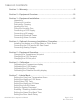
TABLE OF CONTENTS Section 1 – Warranty…………………………………………………………………..5 Section 2 – Equipment Overview…………………………………………………. 10 Section 3 – Equipment Installation……………………………………………….. 12 Unpacking Choosing a Location Preliminary Cleaning Leveling the Unit Filling the Humidity Pan Connecting a CO2 Supply Connecting a N2 supply Connecting Electrical Power Connecting Alarm Contacts Section 4 – Optional Accessory Installation / Operation……………………...
Configuring Temp / CO2 / RH / O2 Alarm Relay Selecting Language Setting System Date / Time Resetting Factory Defaults Section 8 – Datalogging……………………………………………………………..41 Setting the Data Log Time Period Reviewing Data Logs Section 9 – Using the Automatic Decon Cycle…………………………………. 43 Section 10 – Alarms…………………………………………………………………. 46 Section 11 – Service Mode…………………………………………………………. 47 Section 12 – Preventative Maintenance………………………………………….
SECTION 1- WARRANTY INFORMATION CO2 INCUBATOR LIMITED WARRANTY Please review this section before requesting warranty service. At CARON, one of our primary goals is to provide customers with high levels of personal service and top quality products, delivered on time, backed by technical service and supported for the life of the product. Before contacting us for warranty service, please be aware that there are repairs that are not covered under warranty. WARRANTY DEFINED Caron Products & Services, Inc.
This writing is a final and complete integration of the agreement between CARON and the customer. CARON makes no other warranties, express or implied, of merchantability, fitness for a particular purpose or otherwise, with respect to the goods sold under this agreement. This warranty cannot be altered unless CARON agrees to an alteration in writing and expressly stated herein shall be recognized to vary or modify this contract. Ohio Law governs this warranty.
EQUIPMENT INTERNATIONAL LIMITED WARRANTY Please review this section before requesting warranty service. At CARON, one of our primary goals is to provide customers with high levels of personal service and top quality products, delivered on time, backed by technical service and supported for the life of the product. Before contacting your distributor for warranty service, please be aware that there are repairs that are not covered under warranty. WARRANTY DEFINED Caron Products & Services, Inc.
This writing is a final and complete integration of the agreement between CARON and the customer. CARON makes no other warranties, express or implied, of merchantability, fitness for a particular purpose or otherwise, with respect to the goods sold under this agreement. This warranty cannot be altered unless CARON agrees to an alteration in writing and expressly stated herein shall be recognized to vary or modify this contract. Ohio Law governs this warranty. Caron Products & Services, Inc.
INTERNATIONAL SYMBOLS AND DEFINITIONS ? Help i Information Warning of hazardous area Warning of hot surface Warning of dangerous electric voltage Earth (ground) protective conductor WARNINGS Local government may require proper disposal 6400/6404 Series Operations Manual Page 9 of 54 Rev F 09/18/14
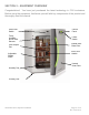
SECTION 2 – EQUIPMENT OVERVIEW Congratulations! You have just purchased the latest technology in CO2 incubators. Before using the equipment, familiarize yourself with key components of the product and thoroughly read this manual.
SECTION 2 – EQUIPMENT OVERVIEW – CONTINUED INCUBATOR CONTROL PANEL 2 5 10 7 11 3 1 4 12 8 6 9 1 Silence Key – Press to Silence audible alarm 7 Message Center – Displays incubator setpoints and any alarm conditions 2 Alarm Indicator – Illuminates on and off during an alarm condition 8 Menu Select – Allows user to select programming menu 3 Heat Indicator – Illuminates when any system heater is on 9 Enter – Allows user to enter any adjusted system variable 4 Inject Indicator – Illuminat
SECTION 3 – EQUIPMENT INSTALLATION Unpacking Your new unit has been thoroughly packaged to avoid shipping damage. However, the unit should be fully inspected upon arrival before signing for receipt. If the package has visual damage, make notes accordingly on the freight bill and have it signed by the delivery company. In the event of concealed damage after the unit is uncrated, keep the carton and packaging material.
Failure to properly install the provided stacking brackets could result in unit tipping. The incubator specifications were developed by testing the product in controlled environment conditions of 72°F to 77°F degrees with a voltage fluctuation of +/-10%. Operating the incubator outside of these specifications will affect the incubator’s performance. Preliminary Cleaning Your new incubator was thoroughly cleaned prior to leaving the factory.
Before relocating an incubator remove the water in the humidity pan and transfer any product to another incubator. Leveling the Unit Place a level on the middle shelf of the incubator. The cabinet has built in adjustable leveling feet designed to level the unit. Adjust the feet appropriately until the unit sits level left to right and front to back.
Filling the Humidity Pan Use only distilled or deionized water with a resistivity between 50K-CM and 1M-CM and a neutral pH. Using water outside this range will void your warranty. To ensure proper operation, distilled or deionized water is required in the humidity pan. Fill the humidity pan approximately half full of water. Place the pan directly under the hinged airflow duct sitting on the bottom floor of the incubator to insure optimum temperature and humidity response.
If the unit is equipped with an optional built in gas guard system, there will be 2 gas inlets. Each of the inlets should be connected to an individual gas tank as described above. Connecting a N2 supply (for suppressed O2 6404 models) Low levels of oxygen can cause suffocation. The use of O2 monitors and alarms is recommended for areas where N2 is used to suppress oxygen The N2 gas supply should be 99.5% pure and should not contain a siphon tube.
Connecting Electrical Power Connect each incubator to a dedicated grounded circuit. Failure to do so could result in electrical shock. Ensure that there is unobstructed access to the main power plug disconnect. Model 6400-1 requires a 100-130 VAC, 50/60Hz 15A power connection. The power cord connection is a NEMA 5-15P plug. Model 6400-4 requires a 220 – 240 VAC, 50/60Hz, 16A power connection. The power cord connection is a CEE 7/7 plug.
SECTION 4 – OPTIONAL ACCESSORY INSTALLATION Installing the units on a Roller Base or Floor Stand This product weighs approx. 250 pounds. Ensure that sufficient resources are available to safely move the product. When moving your incubator, do not lift the unit by the door handle or the outer door as structural damage could occur. Caron offers three different configurations of roller bases and floor stands.
Accessory FLST402 in the figure below provides swivel casters for added mobility to either single or stacked incubators. The two front casters have brakes which can be locked once the unit is rolled to its final location. The unit is designed for a single incubator and elevates it from the floor by approximately 25”.
Connecting Analog Outputs Accessory OUTP401 provides terminals at the rear of the incubator to output analog signals, representing the temperature, CO2, and optional relative humidity levels inside the incubator. Connections can be made to in house data acquisition systems to monitor incubator performance. The accessory can be configured at the factory to supply either 4-20mA or 0-5V signals that represent the parameters.
SECTION 5 – EQUIPMENT OPERATION Once the incubator is properly installed with the humidity pan filled and CO2 source connected, turn on the power switch on the front upper right side of the incubator. When power is applied, the incubator will proceed through a series of startup diagnostics. After this is complete, the incubator will begin to cycle heat and inject CO2. The displays will begin to move toward their setpoints. An inner door switch is located on the front of the unit.
Changing the Temperature Set-point The incubator has an operating temperature range of 20.0°C to 60.0°C. The lowest temperature set-point that the incubator will control temperature is 5°C above ambient. A setting of 20.0°C will disable the temperature control and all heaters and alarms will be disabled.
Changing the CO2 Set-point The incubator has an operating CO2 range of 0.0% CO2 to 20.0% CO2. A setting of 0.0% CO2 will disable the CO2 control and all CO2 control and alarms.
Changing the O2 Set-point The incubator has an operating O2 range of 20.6% O2 to 1.0% O2. A setting of either 20.7% or 1.0% O2 will disable the O2 control and all O2 control and alarms.
SECTION 6 – CALIBRATION After the incubator has stabilized at the user selected setpoints, the control systems can be calibrated. When in calibration mode, the temperature display, CO2 display, and rh display (optional) can all be adjusted to match a reference standard. Before any system is calibrated it is critical that the incubator has been allowed to stabilize properly. In the instructions below, each individual system has a recommended stabilization time that is required before calibration.
Calibrating the CO2 Display A port is available in the center of the inner glass door to allow an air sample to be drawn from the incubator. If the incubator has just been installed and started up, allow 8-12 hours for the incubator to stabilize before making a calibration adjustment. If the unit has been in operation, allow a full hour after the display reaches the CO2 setpoint before making any calibration adjustments.
Calibrating the Relative Humidity Display If your incubator is equipped with an optional humidity sensor and display, the humidity system can be calibrated. If the humidity option was not purchased, the calibration menus will not be displayed in the calibration mode. Place the relative humidity reference device to which the incubator temperature will be calibrated to in the center of the chamber.
Calibrating the O2 Display Independent device calibration A port is available in the center of the inner glass door to allow an air sample to be drawn from the incubator. If the incubator has just been installed and started up, allow 8-12 hours for the incubator to stabilize before making a calibration adjustment. If the unit has been in operation, allow a full hour after the display reaches the O2 setpoint before making any calibration adjustments.
Ambient reference calibration The O2 sensor may be calibrated by using the ambient air as a reference. This process involves filling the incubator with ambient air and then setting the O2 calibration reading to the expected O2 level.
SECTION 7 – ADMIN MODE Many incubator settings are set to common defaults to minimize initial setup of the incubator. However, these settings are also adjustable to allow a user to customize the incubator. These adjustments are all available in ADMIN Mode. Setting Over/Low Temperature Alarm Level The incubator has both an over and low programmable temperature alarm. The factory default for the over temperature alarm is 1.0°C above setpoint. The factory default for the low temperature alarm is 1.
Setting High/Low CO2 Alarm Level The incubator has both a high and low programmable CO2 alarm. The factory default for the high CO2 alarm is 1.0% above CO2 setpoint. The factory default for the low Temperature alarm is 1.0% below CO2 setpoint.
Setting New CO2 Tank (for unit without the optional gas backup switch system) The CO2 tank depletion reminder automatically calculates how much CO2 gas is left in the tank. It alerts the user approximately one week before the gas is depleted which gives the user some buffer time to order new tanks.
Setting High/Low O2 Alarm Level (suppressed O2 model 6404s only) The incubator has both a high and low programmable O2 alarm. The factory default for the high O2 alarm is 1.0% above O2 setpoint. The factory default for the low Temperature alarm is 1.0% below O2 setpoint.
Setting Low RH Alarm Level (for unit with optional RH display) The incubator will display/sound the alarm when the RH level goes below the low %RH alarm value. The default low %RH alarm is 75%.
Setting a System Password (PIN) It is optional to setup a system password to limit access to the control panel functions. If the control panel is protected by a password, you cannot go into the menus until the PIN is entered. The factory default is 0000 which does not limit access to these menus.
Enabling / Disabling Audible Alarm The incubator is equipped with an audible and visual alarm. The audible alarm can be silenced if an alarm condition occurs by pressing the silence key. However, the alarm will ring back if the alarm condition is not corrected or a new alarm condition occurs (see Alarm, Section 11 for more details).
Setting the Alarm Ring Back Time The incubator is equipped with an audible alarm ring back timer. The ring back timer will begin when an alarm is silenced using the silence key on the control panel. When the ring back timer hits the programmed value, the audible alarm will sound again, reminding the user that the alarm condition needs addressed. The factory default for the alarm ring back timer is 15 minutes.
Setting the Door Alarm Delay The incubator has a programmable door alarm delay that can be set between 1 to 15 minutes. The factory default is 15 minutes.
Configuring the Temp / CO2 / RH / O2 Alarm Relay The incubator is equipped a set of dry alarm contacts. Rating of the relay contacts is a maximum of 30V DC, 2A. A set of NO (normally open) and NC (normally closed) contacts are available on the back of the incubator. The software can configure the relay so it changes state during a temperature or CO2 alarm.
Selecting Language A user may select one of two languages for the control panel display including English, and Spanish. The default language is English.
Setting System Date / Time The incubator is equipped with a real time clock that keeps track of date and time even when power is off. Accurate date and time stamping are necessary for the data logging feature. The 24 hour clock is factory set to US Eastern Standard Time.
Resetting Factory Defaults A user can reset factory defaults for temperature and CO2 setpoints and alarm conditions by selecting Reset Defaults.
SECTION 8 – DATALOGGING The incubator is equipped with a built in data logging system. The data logger records time stamped records of temperature, CO2, and humidity/O2 (if equipped) that can be viewed on screen. The information is valuable in determining performance of the incubator.
Reviewing Data Logs Time stamped data log information can be viewed on screen and the history scrolled through. To review the data logs of a particular parameter: 1) Press the key from the main menu 2) Press the to select Data Logging 3) Press the key to enter Data Logging 4) Press the 5) Press the 6) Press the 7) Press the to select Parameter that you want to view key to enter view the data logs to view the scroll through data logs.
SECTION 9 – USING THE AUTOMATIC DECON CYCLE The incubator is equipped with a built-in automatic 90°C moist heat decontamination cycle. The cycle is designed to decontaminate the entire interior workspace including all installed components. Moist heat at 90°C is proven to effectively kill common organisms known to contaminate incubators. The decon cycle consists of a heating phase in which the temperature and humidity rise to approximately 90°C and 60% relative humidity.
You are then prompted to remove the IR CO2 sensor. Follow the instructions below to remove the IR sensor. Failure to remove the IR sensor or O2 sensor (if equipped) during the moist heat decontamination cycle will damage the sensor(s). Remove the two thumbscrews and lower the top air duct from inside the incubator as shown below: Disconnect the cable from the CO2 sensor by rotating the connector counter clockwise and store the sensor in a safe place until it can be replaced following the decon cycle.
The decon cycle is now initiated. Do not open the outer door during the decontamination process. The message center on the display will notify you how much time remains to complete the cycle and when the cycle is complete. The total time to complete the decon cycle will vary slightly depending upon ambient conditions and line voltage to the incubator. The overall time to complete the cycle is approximately 15 hours.
SECTION 10 – ALARMS A sophisticated alarm system monitors all system parameters for any fault condition. At the same time, built in alarm delays protect the user from nuisance alarms created by routine use such as door openings.
SECTION 11 – SERVICE MODE Your CARON incubator has a built in read only Service / Diagnostics mode that can provide information regarding operation of the incubator for troubleshooting purposes. There are no adjustments available or necessary in this mode. The screens available in this mode allow a service technician to quickly troubleshoot any system level problems that occur with the incubator.
SECTION 12 – PREVENTATIVE MAINTENANCE Your CARON incubator is robustly designed to minimize performance problems. However, regular maintenance is very important for continuous trouble free operation. As a general rule, CARON recommends an annual calibration check of the temperature, humidity (optional), and CO2 systems. CARON offers a full range of on-site calibration and validation services. We also offer preventative maintenance contracts on our equipment.
SECTION 13 – SPECIFICATIONS Model 6400-1 6400-4 Temperature Range 5°C above ambient to 60°C Temperature Control ±0.1°C at 37°C Temperature Uniformity ±0.3°C at 37°C Temperature Sensor Precision Thermistor Humidity Range Elevated up to 95% @ 37°C CO2 Range 0-20% CO2 CO2 Control ±0.1% CO2 CO2 Sensor Infrared CO2 Sensor O2 Range 20-1% O2 O2 Control ±0.1% O2 O2 Sensor Fuel Cell Interior Dimensions 20”W x 21”D x 25”H (50.8 cm x 53.3 cm x 63.
SECTION 14 – ELECTRICAL SCHEMATICS 6400-1 110-130V 50/60 HZ, SINGLE PHASE, 7.
SECTION 14 – ELECTRICAL SCHEMATICS 6400-4 220-240 VAC, 50/60 HZ, SINGLE PHASE, 3.
DECLARATION OF CONFORMITY In accordance with EN 45014:1998 We, based at: Caron Products and Services, Inc.