MODEL 6105 FINGERPRINT DEVELOPMENT CHAMBER OPERATIONS MANUAL PO Box 715 Marietta, OH 45750 800-648-3042 740-373-6809 Fax 740-374-3760 www.caronproducts.com service@caronproducts.
Dear Valued Customer: Thank you for purchasing CARON Products & Services equipment. We appreciate your business and look forward to being your preferred supplier of controlled environment equipment products in the future. At CARON, we are committed to continuous quality improvement. Our goal is to supply our customers with highly reliable equipment at a fair price. In order to openly monitor our performance, we would appreciate your feedback on our products and services.
EQUIPMENT LIMITED WARRANTY Please review this section before requesting warranty service. At CARON, one of our primary goals is to provide customers with high levels of personal service and top quality products, delivered on time, backed by technical service and supported for the life of the product. Before contacting us for warranty service, please be aware that there are repairs that are not covered under warranty. WARRANTY DEFINED Caron Products & Services, Inc.
Please review this section before requesting warranty service. At CARON, one of our primary goals is to provide customers with high levels of personal service and top quality products, delivered on time, backed by technical service and supported for the life of the product. Before contacting your distributor for warranty service, please be aware that there are repairs that are not covered under warranty. WARRANTY DEFINED Caron Products & Services, Inc.
TABLE OF CONTENTS SECTION PAGE INTRODUCTION ................................................................................ 6 INSTALLATION ................................................................................. 8 Power requirements ......................................................................... 9 Water connections ........................................................................... 9 OPERATION .......................................................................................
INTRODUCTION CARON’s 6105 fingerprint chambers are designed specifically to create conditions for developing DFO, Ninhydrin, and other fingerprint development process prints. The chamber features rapid condition recovery after the chamber door is opened and closed. The large viewing area offers easy observation of critical samples. The chamber interior is made of high quality, corrosion resistant material.
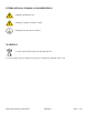
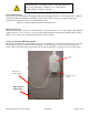
INTERNATIONAL SYMBOLS AND DEFINITIONS Warning of hazardous area Warning of dangerous electric voltage Earth (ground) protective conductor WARNINGS Local government may require proper lamp disposal Use eye protection, gloves and aprons if exposure to hazardous materials could occur Model 6105 Operations Manual Rev I 03/03/2014 Page 7 of 22
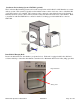
INSTALLATION Unpacking This product has been completely tested, cleaned and packed for shipment. Carefully remove all packing material. Please examine the chamber completely. Should any damage be found, notify the delivering carrier immediately. Report any shortages to your local distributor or contact CARON customer service at 740-373-6809, 800-648-3042 (USA only) or service@caronproducts.com. Caron provides full on-site installation services for all models.
Connect the unit to a dedicated grounded outlet that matches the units power requirements. Failure to do so could result in electrical shock or damage to the unit. Power Requirements The power cord of this chamber is equipped with a grounded plug. Be sure to connect the ground. CARON recommends that the chamber have a dedicated wall outlet. Verify correct power supply required for particular unit. (Nema 6-15 15A Cord, Model 6105-2 only.
Condensate Recirculating System: CRSY102 (optional) The Condensate Recirculating System can be used in conjunction with CARON’s 6105 chambers as a water delivery system. This system is typically used in facilities where a drain or in-house source of distilled, RO or deionized water is not available. The system provides continuous, clean, filtered water to the chamber’s humidity injection system, collects and recycles the condensate that forms in the base of the chamber.
OPERATION Start Up Be sure the water connections are properly made and the exhaust vent properly closed (see installation section). Turn on unit by pressing the power switch. The ‘power on’ indicator light, temperature and timer displays will illuminate. Air should be gently circulating internally.
Temperature Infinity/Home button Actual temperature Up button Temperature set point Down button EZ button Advance button The unit is capable of reaching temperatures that could result in burns. Always wear protective clothing when accessing the unit. Use caution when opening the outer door. Change Set Point Use the up and down arrow push-buttons to obtain the desired temperature set point (red upper display). The temperature is displayed in ºC.
Countdown Timer The countdown timer provides users with a way to alert them to check or remove chamber contents. It does not turn the chamber off or in any way or affect the temperature and humidity control. Time is displayed in minutes and seconds. Start button Reset button Time remaining Total countdown time Unused buttons Up and down arrow buttons Using the timer 1. Set total countdown time to desired value using the four up and down arrow buttons. 2. Press the start button. 3.
Humidity For fingerprint development processes that require humidity such as Ninhydrin, 1,2-Indanedione, Nickel Nitrate, 5-MTN, Zinc Chloride, the humidity should be enabled. To enable humidity control, turn the humidity control enable switch on. This turns on the humidity controller display and fills the steam generator with water. When the humidity switch is enabled, the glass viewing window is heated to minimize the condensation on the inside.
Change Set Point Low water level alarm light Infinity/Home button Actual humidity Up button Humidity set point Down button EZ button Advance button Use the up and down arrow push-buttons to obtain the desired humidity set point (red upper display). The relative humidity is displayed in %. To turn off the humidity control system, but still display the chamber humidity level, press the EZ button. The words “OFF” will display in the set-point area.
Viewing light To illuminate the interior, turn on the light switch. If lighting does not come on, see troubleshooting guide.
CALIBRATION The temperature and humidity systems can all be calibrated as necessary. CARON recommends an annual calibration check of each system. Before making a calibration adjustment, allow the cabinet to stabilize a minimum of 12 hours from a power off condition. If the unit has been in operation, allow a minimum of 3 hours of stable operation at all set-points.
MAINTENANCE The CARON chamber has been robustly designed to minimize performance problems. However, regular maintenance is very important for continuous trouble free operation. As a general rule, CARON recommends an annual calibration check of the temperature, and humidity systems. CARON offers a full range of on-site calibration and validation services. We also offer preventative maintenance contracts on our equipment.
Brief Troubleshooting Unit won’t reach temperature set point Is the set point within the unit specification range? Is the rear vent closed? Is the door closed and latched? Can air flow freely throughout the chamber? Inhibited air flow can trip the over temperature safety device.
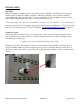
Interior lights won’t come ‘on’ Are lights turned ‘on’? Is the connector on the bottom of the door switch connected (see below)? Door connector Glass fogs up on inside Is the humidity switch on? Is the connector on the bottom of the door switch connected (see picture)? Is the door sealed tightly? Is the door gasket collapsed? Has the unit stabilized 1 hour? Spare Replacement Parts Model 6105 Operations Manual Rev I 03/03/2014 Page 20 of 22
General Part Number MTR-107 BLW-110 CTR-122 POW-108 CRD-108 GSK-136 LGT-143 Description BLOWER MOTOR BLOWER WHEEL WATLOW STANARD CONTROLLER 24V POWER SUPPLY LINE CORD 50 HZ ONLY DOOR GASKET DOOR LIGHT Temperature Related Part Number HTR-143 RMT-114 RMT-115 RTD-101 REL-103 Description AIR HEATER SNAP DISK 225 F THERMAL FUSE 169 C TEMPERATURE SENSOR HEATER SOLID STATE RELAY Humidity Related Part Number HUM-114 SOL-133 SOL-135 LEV-106 HTR-144 REL-103 CTR-124 REL-150 Description RH SENSOR HUMIDIFICATION
CE Compliant Product Declaration of Conformity Caron Products 27640 State Route 7 Marietta, OH 45750 USA Declares that the following product: Designation: Model Number: Classification: Rated Voltage: Rated Frequency: Rated Power Consumption: 6105 6105-3 Electrical Equipment for Measurement, Control, & Lab Use 220-240 V~ (ac) 50Hz 15 amps Meets the essential requirements of the following European Union Directive(s) using the relevant section(s) of the normalized standards and related documents shown: 89/