
User's Manual
Trailblazer Installation and User Manual version 1.03 30
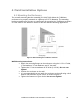
4.4 Weatherproofing RF Connections
Once you have the antenna mounted and secured. Complete the installation by
properly attaching the weatherproof cables.
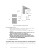
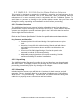
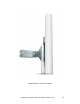
4.5 Antenna Alignment
Rough alignment: This is fairly straight forward. Since it is a prerequisite that
you have line of sight between the two points, here are several ideas that have
worked for installers:
If you can see the other unit, simply aim the units towards each other.
During midday, use a mirror or compact disk to create a reflection
approximately towards the other site while someone watches for the flash.
Plot out the path on a topographical map and set the antennas using a
compass.
How close in alignment do they need to be? +/- 6 degrees will be adequate
for most paths using the 16 dB gain antenna. Certain paths that have a low fade
margin may require a more accurate setting.
Alignment indicators: Due to the nature of digital modulation and the
associated circuitry, there is no analog test point at which the signal strength may
be monitored. Rather, the bit error rate is indicated on the digital board. If there
are obstructions or interference in the link the middle, red LED will begin to blink.
The rate of flash is an indication of the degree of signal degradation, with a
higher flash rate indicating more errors.
Final alignment is performed by connecting a standard telephone directly to the
CPE terminal (FXS) and listening to the dial tone. As the antenna is moved to
the left the signal will degrade, the bit error LED will flash, and eventually the link
will be lost. Note where the antenna is aimed when the link is lost and rotate the
antenna to the other side until the signal is lost again. The midpoint between the
positions where the signal was lost indicates the best antenna position. Use the
GUI software and a laptop to determine the exact signal peak and then tighten
the antenna mounts.
4.6 Interference Solutions
Sometimes after installation, final alignment is found to interfere with external
devices, and/or external devices are later installed that affect the Carlson
Wireless Radio device. To determine if the Carlson Wireless radio is an
interferer, power down the radio unit and check if the interference is removed.
To determine if an external device is interfering with the Carlson Wireless radio,
shut down suspected devices while listening to an audible tone (such as dial
tone) on a phone connected through the Carlson Wireless system.