
User's Manual

Trailblazer Installation and User Manual version 1.03
11
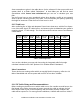
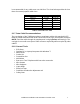
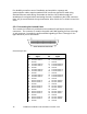
Cable Size
(A.W.G.)
(mm)
Ohms/100ft
(both legs )
feet per Ohm
(both legs)
if feeding 13.8,
distance with 5%
(voltage loss 2pr.)
if feeding 24,
distance with 5%
(voltage loss 2pr.)
14
1.63
0.516
194
1783
6202
16
1.29
0.818
122
1125
3912
18
1.09
1.302
77
707
2458
19
0.91
1.642
61
560
1949
22
0.64
3.3
30
279
970
24
0.51
5.24
19
176
611
26
0.41
8.32
12
111
385
Table 4: Feed Cable Sizing and Distance for the Traiblazer
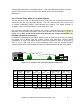
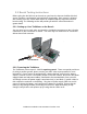
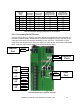
2.3.3 Connecting the POTS Lines
Connect POTS lines as shown in the figure below using the black screw terminals on
the units’ interface cards. Remember to connect the telephone line(s) from the phone
company to the Base unit and the handset(s) to the CPE unit. The location of your
active lines will depend on the time slots selection made by the CPE and the bandwidth
used. Note the “Active Line” label on your Base and CPE units.
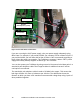
Connecting POTS lines, Repeater, and Sync
CPE
#0
Line 2
Line 1
CPE
#1
Line 2
Line 1
CPE
#2
Line 2
Line 1
CPE
#3
Line 2
Line 1
Repeater
Ports
Repeater “A”
Repeater “B”
Sync
Port
RJ45
Screw
Terminals
10BaseT
Port
Ethernet