
User's Manual

Trailblazer Installation and User Manual version 1.03
5
a reasonable signal at the receiving antenna. This three dimensional space is called
the RF LOS or Fresnel zone for the French physicist who first discovered its
importance.
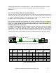
2.1.4 Fresnel Zone: What it is in plain English!
The Fresnel zone is the tree dimensional cone around the line-of-sight that radio waves
spread out into after they leave the antenna. The cross section of the first Fresnel zone
is circular; subsequent zones’ cross sections are annular. The signal strength is
strongest in zone 1 and decreases in each successive zone.
Not only trees, buildings and mountains can occupy a Fresnel Zone, the curvature of
the earth, even for some short paths, also has to be taken into consideration. A rule of
thumb is that 60% of the first Fresnel zone must be free of any obstructions for
tolerable attenuation of the signal.
In addition to absorbing the RF signal, objects in the RF path can also reflect it, making
the signal out of phase with the original signal, and effectively causing signal
cancellation. In zone 1 the signal will be 0 to 90
o
out of phase in zone 2, 90 to 270
o
in
zone 3, 270 to 450
o
and so on. Even numbered zones have the maximum phase
canceling effect and in odd numbered zones the reflected waves will add to the signal.
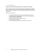
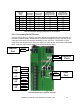
Fresnel Zone
Line of Sight
Figure 1: Line of Sight is clear, the first Fresnel Zone is NOT clear.
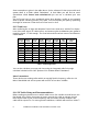
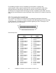
Zone
Frequency
(MHz)
Wavelength
(feet)
Distance to
start
(miles) (km)
Distance to
end
(miles) (km)
Fresnel Radius
(feet) (m)
60% of Zone
(feet) (m)
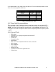
1
2400
0.41
2.0
3.2
2.0
3.2
46.53
14.18
27.92
8.51
2
2400
0.41
2.0
3.2
2.0
3.2
65.80
20.06
39.48
12.03
1
2400
0.41
1.5
2.4
4.5
7.2
49.35
15.04
29.61
9.03
1
2400
0.41
3.0
4.8
3.0
4.8
56.98
17.37
34.19
10.42
1
2400
0.41
4.0
6.4
10.0
16.0
78.65
23.97
47.19
14.38
1
2400
0.41
6.0
9.6
6.0
9.6
80.59
24.56
48.35
14.74
1
2400
0.41
12.0
19.2
12.0
19.2
113.97
34.74
68.38
20.84
Table 1: Fresnel Zone Chart