
User's Manual

Trailblazer Installation and User Manual version 1.02 42
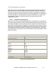
6.3 Cable Pin outs
Should you misplace or lose your serial programming cable, you can call your
CWT sales rep. and order a replacement or construct a new cable from a few
simple parts using the diagram below.
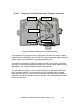
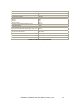
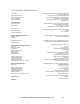
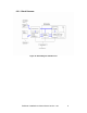
6.3.1 Configuration Port Pinout
Configuration Port Cable Construction Table
A DB9 pin Female to be fit in the PC is wired
with:
A 3 pin, .100” spacing connector, female,
connecting to the Trailblazer as shown:
DCD on pin 1, (not used)
TX Data on pin 2, TX Data on pin 1,
RX Data on pin 3, RX Data on pin 3,
DTR on pin 4, (not used)
SG on pin 5, (signal ground) SG on pin 2, (signal ground)
DSR on pin 6, (not used)
RTS on pin 7, (not used)
CTS on pin 8, (not used)
RI on pin 9, (not used)
Table 15: Configuration Port Cable Construction Table
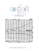
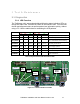
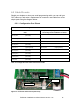
Figure 13: Serial Data Cable Pinout (PCB View)
TRANSMIT
GROUN
D
RECEIV
E