
User's Manual

Trailblazer Installation and User Manual version 1.02 37
5 Test & Maintenance
5.1 Diagnostics
5.1.1 LED Function
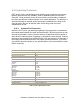
The Trailblazer units’ are equipped with multifunction status indication LEDs on
the top and radio card. There are no LEDs on the interface card. You can read
the link and alignment status as well as packet loss information quickly, without
using a PC. Use the table below for translating the LED patterns.
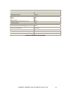
CPE Unit BASE Unit
D4 D5 D6 D4 D5 D6
Description
NO POWER
Off Off Off Off Off Off
Power system failure or no power applied
POWER ON
Off Off Solid Off Off Solid
Initial Power up, FPGA not loaded by CPU
CPE
ACQUIRING
Solid Solid Flashing Off Solid Flashing
CPE – receiver on, looking for valid signal.
Base - FPGA loaded, radio transmitting
CPE
RANGING
Solid Off Flashing Off Solid Flashing
CPE acquired and locked, CPE begins
transmitting locator beacon
BASE
RANGING
Solid Off Flashing Solid Off Flashing
Base accepts CPE locator beacon and
begins ranging operation
ALIGNMENT
Off Blinks Solid Off Blinks Solid
Final alignment, minimizing bit errors
LOCKED
Off Off Flashing Off Off Flashing
Units locked and aligned, ready for service
PACKET
ERRORS
Off Blinks Flashing Off Blinks Flashing
D5 blinking indicates packet errors, weak
signal or interference
Table 14: System Status LED Information Table
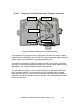
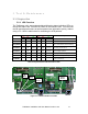
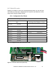
Figure 11: Trailblazer Radio Card LEDs
D4
(
Red
)
Reset
Button
D5
(
Red
)
D6
(
Green
)