
User's Manual

Trailblazer Installation and User Manual version 1.02 33
4.10 Lightning Protection
CWT stocks in-line, gas-discharge style lightning surge suppressors as primary
lightning protection for their reliability, ease of installation and low cost to the
customer. In-line protectors mount in series with the coaxial cable or telephone
line which provides an excellent solution for a retrofit application. The protector is
grounded through an external ground screw that is attached to the body of the
surge protector. Be sure to take the other end of this ground circuit into
consideration as well.
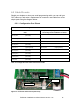
4.10.1 Antenna Port Protection
Mount the CWT in-line, gas discharge lightning surge suppressor in parallel with
the coaxial cable between the radio and the antenna. Place the protector as near
the radio as possible in order to limit the amount of cable that will be exposed to
either direct or indirect strikes of lightning or atmospheric static charges. Connect
the largest wire (usually #8 or #10AWG solid) to the ground screw on the body of
the surge protector and terminate it to a proper ground (see above). If you have
any question about the quality of your ground system, stop and remedy the issue
before continuing.
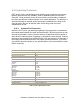
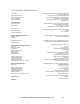
RF Gas Discharge Lightning Surge Protector Specifications
CWT Part number 640-6600
Description High Frequency co-axial surge protector (Gas tube)
Maximum power (50 Ohms) 70 W
Breakdown Voltage (100 V/s) 90-130 V
Residual Voltage (1 kV/µs) < 600 V
Power Handling (8/20 µs waveform)
10 shocks
1 shock
10 kA
20 kA
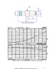
Return Loss and Attenuation
@ 0.5 GHz
@ 1 GHz
@ 4 GHz
< -25 dB
< - 25 dB
< -20 dB
Insertion Loss
@ 0.5 GHz
@ 1 GHz
@ 2.5 GHz
@ 4 GHz
< 0.05 dB
< 0.03 dB
< 0.067 dB
< 0.29 dB
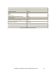
Connector Type “N”
Housing Material Copper alloy with CuZnSn finish
Contact Sockets Material Gold Plated Copper alloy
Insulation Material Teflon per ASTM-D-170
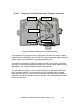
Table 12: RF Lightning Protection