
User's Manual

Trailblazer Installation and User Manual version 1.02 30
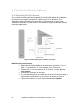
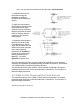
Hint: You may want to complete the first two steps on the ground!
1. Assemble the mount to
the antenna using the
hardware provided as
described in the diagram to
the left.
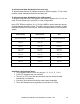
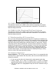
2. Adjust the nuts nearest
the antenna to positions that
will provide the tilt angle
required. Use the mounting
diagram (left) with the table
below to roughly align the
antenna to your position
requirements.
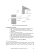
3. Assemble the antenna to
the mast as shown at left.
Fine adjustment to the tilt
angle can be made after the
antenna has been mounted
to the mast. Spacing
references for downtilt (L1,
L2) will be as shown (left).
Spacing references for
uptilt (L1, L2) will be
opposite as shown (left).
Once the antenna has been mounted, aligned and tested be sure to properly
complete the installation by weatherproofing the cable connections. See Section
4.5 “23dBi 5.8 GHz Directional Flat Panel Antenna
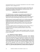
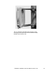
This antenna is similar to the 18dBi 2.4 GHz antenna except that it is properly
polarized when the arrow on the back indicates a vertical line. This results in a
diamond shape presented.
4.4 22dBi 4.9 GHz Directional Flat Panel Antenna
This antenna is similar to the 18dBi 2.4 GHz antenna except that it is properly
polarized when the arrow on the back indicates a vertical line. This results in a
diamond shape presented.
Weatherproofing RF Connections