
User's Manual

Trailblazer Installation and User Manual version 1.02 21
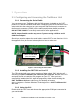
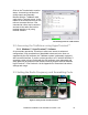
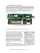
3.3.1 Selecting the CPE Time Slot
Up to (4) CPE units can communicate with each Base unit when used in a STAR
topology. To distinguish between the four CPEs, a different time slot is allocated
to each CPE using the rotary DIP switch located immediately behind the LEDs as
shown in the figure below. Use a non-conductive trim tool to select time slots 0,
1, 2, and 3 to avoid shorting any components. Reset the unit to put your
selection in effect by pressing the reset button located behind the second white
three pin connector as shown.
Figure 5: CPE Time Slot Selection Switch
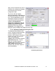
3.4 Allocating Bandwidth to Voice and/or Data
Preceding future integration of these functions into
the GUI software, some system configurations
must be performed on a manual text entry level.
To do this, you can interface with the Trailblazer
radio card using either the GUI software on the
Terminal screen (See Section 3.1.3) or by using
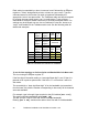
the HyperTerminal™ software. You will also need
to add a 50ms delay to the linefeed in your
terminal ASCII settings in order to send text
commands to the Trailblazer radio through
terminal software. See the screenshot (right) for
an example.
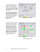
Begin by starting the GUI or making sure your
terminal software is loaded and properly configured to communicate with the
Trailblazer radios. See Section 6.4 for configuration instructions.
CPE Time
Slot
Selector
Reset
Button