
User's Manual
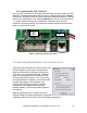

Trailblazer Installation and User Manual version 1.02 14
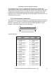
37 Ground 37 Ground
13 E1 13 E5
38 M1 38 M5
14 E2 14 E6
39 M2 39 M6
15 E3 15 E7
40 M3 40 M7
16 E4 16 E8
41 M4 41 M8
17 Ground 17 Ground
42 Ground 42 Ground
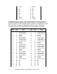
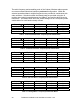
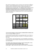
If a standard telephone cable is used, the connections may be brought to pre-
wired punch blocks using two 25 pair telephone cables. The location of the
signals is shown in the following table as they appear on a standard punch block.
The punch block terminals are numbered from top to bottom. The 50 pin
Centronics connector pins (abbreviated Ctrnx) are included for reference.
50 pin
Ctrnx
Punch
Term
Signal
name
50 pin
Ctrnx
Punch
Term
Signal
name
26 1 Transmit Audio 1- 26 1 Transmit Audio 5-
1 2 Transmit Audio 1+ 1 2 Transmit Audio 5+
27 3 Transmit Audio 2+ 27 3 Transmit Audio 6+
2 4 Ground 2 4 Ground
28 5 Ground 28 5 Ground
3 6 Transmit Audio 2- 3 6 Transmit Audio 6-
29 7 Transmit Audio 3- 29 7 Transmit Audio 7-
4 8 Transmit Audio 3+ 4 8 Transmit Audio 7+
30 9 Transmit Audio 4+ 30 9 Transmit Audio 8+
5 10 Ground 5 10 Ground
31 11 Ground 31 11 Ground
6 12 Transmit Audio 4- 6 12 Transmit Audio 8-
32 13 Receive Audio 1- 32 13 Receive Audio 5-
7 14 Receive Audio 1+ 7 14 Receive Audio 5+
33 15 Receive Audio 2+ 33 15 Receive Audio 6+
8 16 Ground 8 16 Ground
34 17 Ground 34 17 Ground
9 18 Receive Audio 2- 9 18 Receive Audio 6-
35 19 Receive Audio 3- 35 19 Receive Audio 7-
10 20 Receive Audio 3+ 10 20 Receive Audio 7+
36 21 Receive Audio 4+ 36 21 Receive Audio 8+
11 22 Ground 11 22 Ground
37 23 Ground 37 23 Ground
12 24 Receive Audio 4- 12 24 Receive Audio 8-
38 25 M1 38 25 M5
13 26 E1 13 26 E5
39 27 M2 39 27 M6
14 28 E2 14 28 E6
40 29 M3 40 29 M7
15 30 E3 15 30 E7