
User's Manual

27
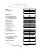
FT-512 Quality Assurance Testing
Engineer _______ Date ________ Serial Number _______
Slave Master
Hardware
1. PC Board Revision # Rev. Rev.
2. Visual Inspection
a. S2 soldered to ground
b. Switch position - (Default 0)
Voltage / Current
3. Test bench voltage (20.0 VDC) VDC VDC
4. Current draw mA mA
5. 5 volt regulator (Measure @ JP18)
6. 3.3 volt regulator (Measure @ JP19)
7. 2.5 volt regulator (Measure @ JP20)
Software
8. Fuse bit programming
9. AtMega program load Version 1. Version 1.
10. FPGA passed LED test Version 1. Version 1.
Configuration port test
11. CDMA Code (1, 2, 3, 4)
12. Set Master / Slave (M, S)
13. Set speed (512, 256, 128, 64)
14. Set serial number
Clocking and Sync
15. Sync. port in/out test
16. Clock speed @ (512, 256, 128, 64)
17. External clock Auto-Sync
18. Co-location sync test
24 Hr Burn-In Assurance Test
Radio Test
19. Radio serial number
20. Freq. with radio on line (32.768 MHz)
21. Freq. Admin and operate
a. V.35 data port bit error test
b. RS_232, DSR, CTS DCD test
22. Radio power @ mid-band dB dB
23. RSSI test with 100dB att. dB dB
Shipping and Assembly
24. Internal antenna gain test
25. External antenna test
Shipped with serial cable
GUI CD Version 2.___