
User's Manual

26
Reset causes are broken down as such:
Power – number of times the supply voltage failed.
External – number of times the manual pushbutton has been depressed.
Brownout – number of times the supply voltage went below the minimum of 10
volts but did not fail completely.
Watchdog – number of times the watchdog initiated a reset.
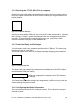
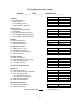
Figure 19: System LED's
4.1.4 LED Function
The LED’s labeled D4, D5 and D6 represent the following functions;
D4 – (SYSTEM ACTIVE) This led is lit if the Microprocessor is trying to connect
or connected.
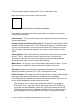
D5 – (PACKT ERR) This will flash for a fraction of a second when the units are
establishing a link and then after the link has been established it should go dark.
It then will light for ½ of a second if it detects any packets with data errors. This
would occur with interference or insufficient path margin.
D6 – (CPU WAKE) This led will flash rapidly once the hardware has completed
the “power on self test” (post) procedure successfully.
4.1.5 In Factory Tests
The following compliance tests are competed in the factory before the product is
shipped:
D4
-
Link Connected?
D5
-
Packet Errors?
D6
-
CPU Awake?