
User's Manual

FT-512 Trailblazer Installation and User Manual version 1.09 21
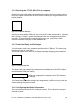
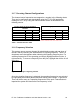
The rotary switch position onboard the FT-512 is also shown here.
Note at the bottom of the screen is a progress bar.
Figure 12 GUI – Configure Screen w/ Progress Bar at Bottom
For trouble free operation, allow the progress bar to complete its task before
selecting other functions.
Serial Number. This is set at the factory and is used by the factory for part and
revision identification.
Setting the Special Field Delimiter number. The Special Field Delimiter (SFD)
number is set by the super user. This is what gives the part it’s uniqueness and
security over the airwaves. You must have the same SFD number in two units
that you want to communicate together. The number must be between 1 and
65534.
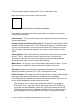
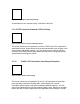
Switch Position. This window will read out what the setting of the rotary switch
on the FT-512 is. Only switch position 0 allows the user to configure the
operating frequencies. Non zero switch settings select the pre-programmed
frequencies that can be seen in the right hand window.
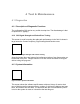
Master/Slave. Of any pair, one is set as Master and the other is Slave. If more
than one pair are collocated, they must be all be Masters at that end.
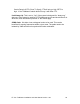
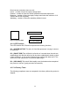
Data Speed. Selection of the desired synchronous data rate is accomplished
with this pushbutton. Choices of 512, 256, 128 and 64 kb/s exist.
DTR Line Active. DTR stands for Data Terminal Ready. It is part of the data port
flow control logic which qualifies data as acceptable or unacceptable.
Considering that the Trailblazer, by default, will emulate the DCE side of a V.35
port, a typical handshaking session would go as such:
If the setting is “yes” , then the unit will operate without a user supplied
DTR signal. If “no”, then the unit must see a high signal on DTR before a
connection can be established. When the Terminal equipment has booted,
DTR will go high, When the Trailblazer’s COM link is up, is ready to accept
and send data, and sees the opposing DTR high, it will raise DCD (Data