
User's Manual

FT-512 Trailblazer Installation and User Manual version 1.09 19
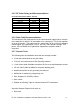
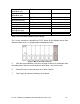
Note: Under normal operation the channel select switch is set to zero, allowing
the Trailblazer to choose from a custom frequency group where it will search for
a clear available channel. This option provides maximum performance and
should be the normal choice. The optional settings detailed above are designed
for quick start testing or to satisfy unique operational requirements such as co-
location or persistent interference issues. For all changes to channel selection
the devices must be reset before the new selection will be acknowledged.
2.5 Field Installation
2.5.1 Bench Testing
Before going into the field it is very important to set up the units on the bench and
become familiar with their operation. Follow the above setup and using the
internal antennas. Full operation should be confirmed before leaving for the field.
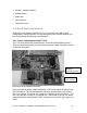
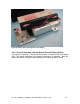
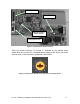
2.5.2 Mounting the Cabinet
Figure 8: Mounting the Cabinet Outside
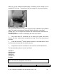
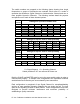
2.5.3 Synchronization of Co-located units
When co-locating more than one device in a given location it is necessary to
synchronize the transmitters at the Master site only such that they transmit and
receive at the same instant. Without synchronization bit errors will result and
may cause calls to be dropped or audio to become intermittent.
The synchronization cable is fabricated and installed to link the internal clock
circuitry of all co-located units. Note that the pin configuration for the first unit is
such that it becomes the master clock for the subsequent connected units.
The cable consists of a DB-9 female connector and a tightly twisted pair CAT 5
rated cable (due to the high speed nature of the signal this type of cabling must
be used).