
User's Manual

FT-512 Trailblazer Installation and User Manual version 1.09 18
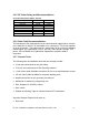
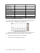
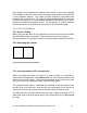
The switch numbers are mapped to the following charts showing how single
frequencies or groups of frequencies are selected. Each refers to a mode of
operation that includes a Signal Channel or Administration Channel and one or
more possible Operation Channels. The following sections detail the purpose
and specific use of each of these channel options.
Switch
Position
Settings for up to 6 co-located units
Ch. 1 Ch. 2 Ch. 3 Ch. 4 Ch. 5 Ch. 6 Ch. 7
1 Operate
Signal
2
Operate
Signal
3
Operate
Signal
4
Operate
Signal
5
Operate
Signal
6
Operate Signal
Switch
Position
Settings for up to 3 units in close proximity
Ch. 1 Ch. 2 Ch. 3 Ch. 4 Ch. 5 Ch. 6 Ch. 7
7 Operate Signal
Operate
8
Signal
Operate
Operate
9
Signal Operate
Operate
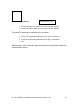
Switch
Position
Settings for up to 2 units in close proximity
Ch. 1 Ch. 2 Ch. 3 Ch. 4 Ch. 5 Ch. 6 Ch. 7
A Operate
Signal
Operate
B
Operate
Signal
Operate
C
Signal
Operate
Operate
D Operate
Operate
Signal
Operate
Table 6: Switch Position Frequency Defaults
S = Signal Channel O = Operating Channel
Switch positions E & F are reserved for future use
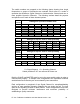
Both the SLAVE and MASTER must be set to the same switch setting in order to
communicate properly. In multiple user configurations the Operation Channels
are distributed such that they are never shared by two transmitters.
Each configuration is comprised of one Signal Channel for setup/handshaking
and two or more possible Operating Channels for use during the call. The time
spent on the Signaling Channel is about 500ms. These configurations have been
designed to provide minimum interference and maximum possibility of
establishing a quality connection.